VGS-35 (Video Glitch System 35)
Modular style glitch-generator for analog video signals


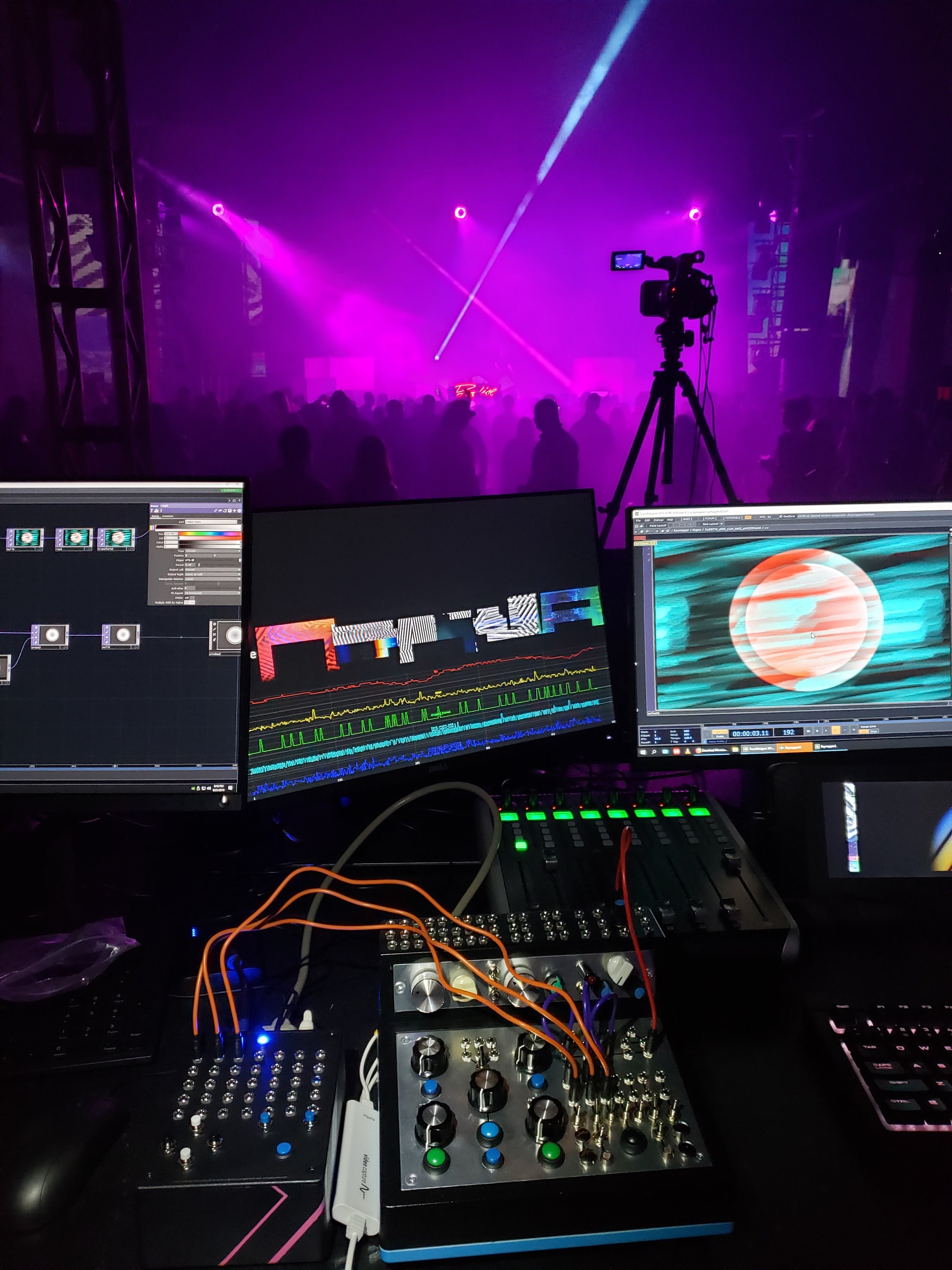
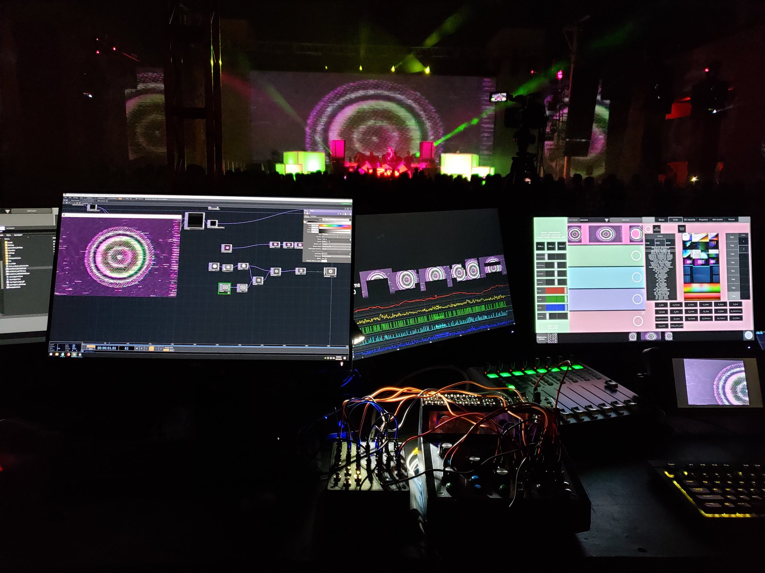
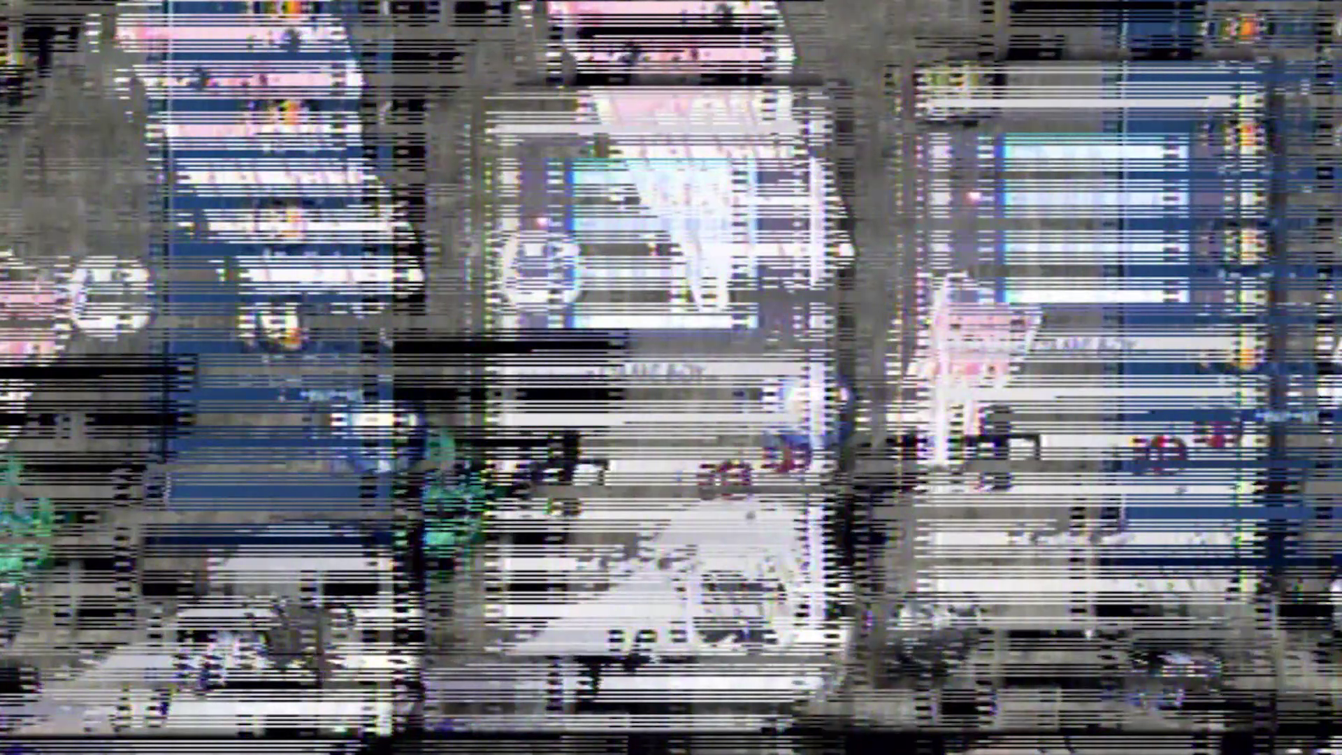
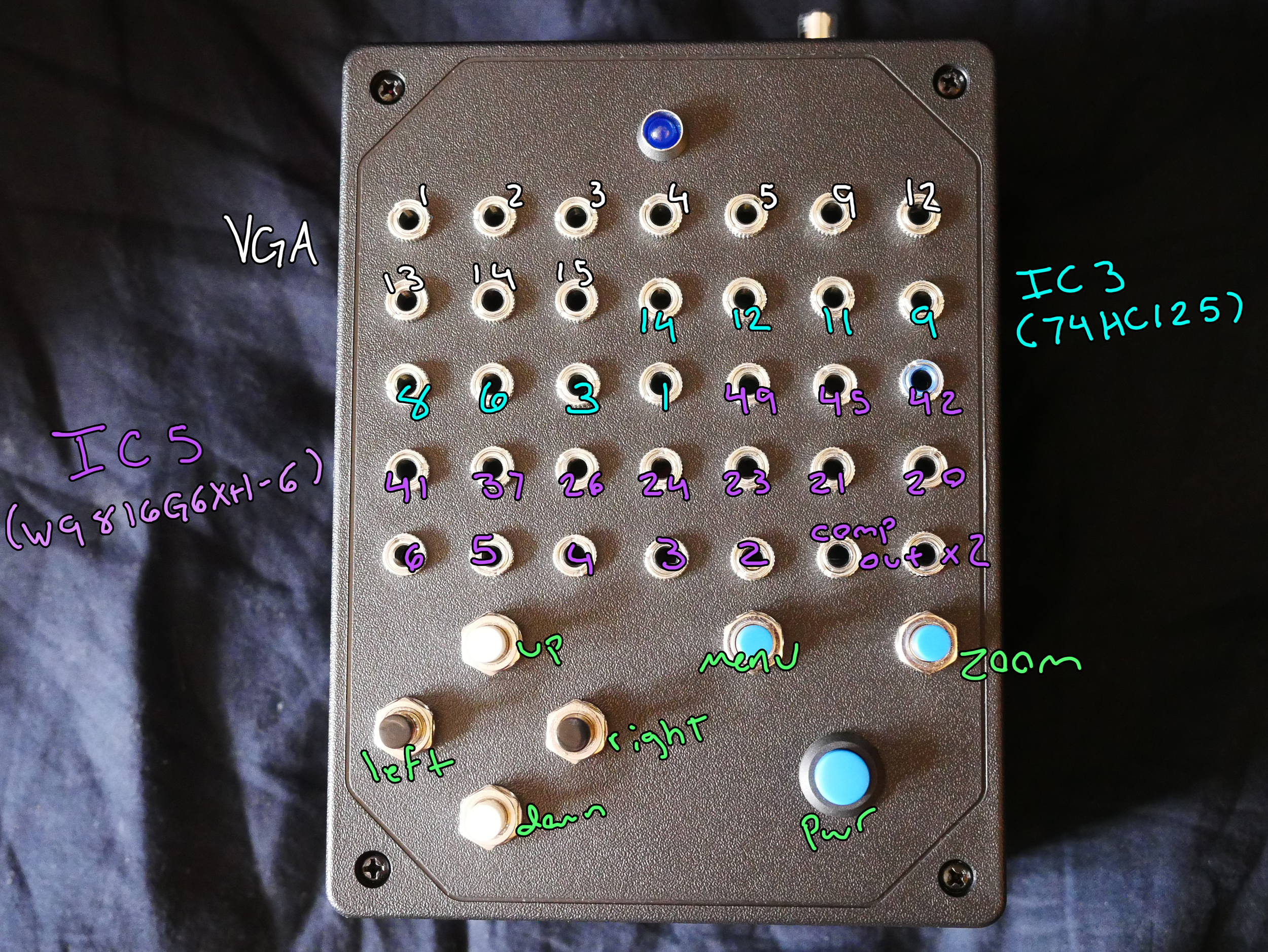
9/2019: The VGS35, or Video Glitch System 35, is a re-housed analog video signal converter that retains all original functionality while exposing the more useful sections of the two main IC chips (74HC125 quad buffer & W9816G6XH-6 SDRAM) and a few other sections of the internal circuitry as a 35 point patchbay. This was built as a companion to my other 2019 build, the ModBox 37 as it easily integrates with it via the patchbay. This allows for building and controlling patch connections, driving visual signals with the MB37’s LTC1799 precision oscillator and LFO, as well as creating audio reactive analog visuals by cross-patching with instruments built for the MB37 such as the Casio SK-1. The patchbay also leaves the device open to having signals from things like function generators injected, which allows you to dial in some really interesting effects based on signal frequency, from simple scanline oscillations to slit-scanning effects.
Essentially, it takes a video signal via VGA, lets you dial in some lofi glitchy goodness, and spits the signal back out as a composite signal. Runs on 5v USB power.
An add-on for this device for creating video feedback loops, the VGS-FB, can be found here.
12/2020: The glitchy patchbay that this thing is all about was used in a recent video synth, The I.F.D.
1/12/2021: A new version of this build in Eurorack module format can be found here.
2/5/2021: This device has been built into GVS008 with a composite video input in place of the VGA input.
Progress & initial test photos
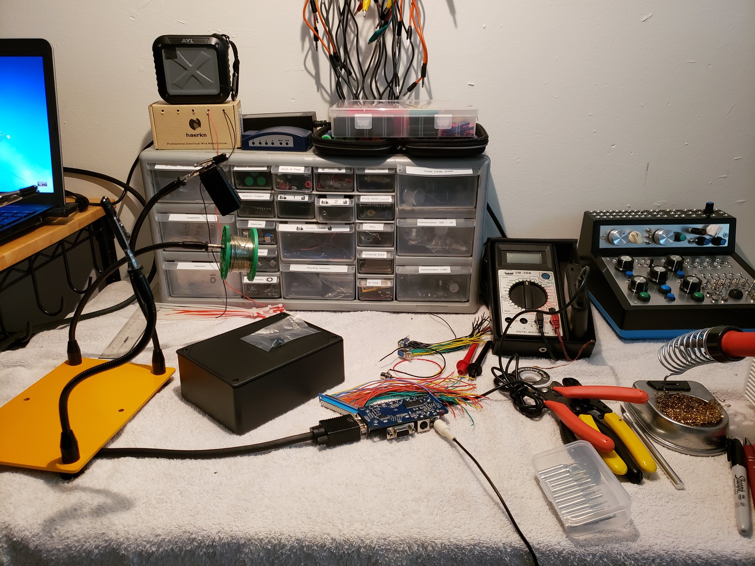
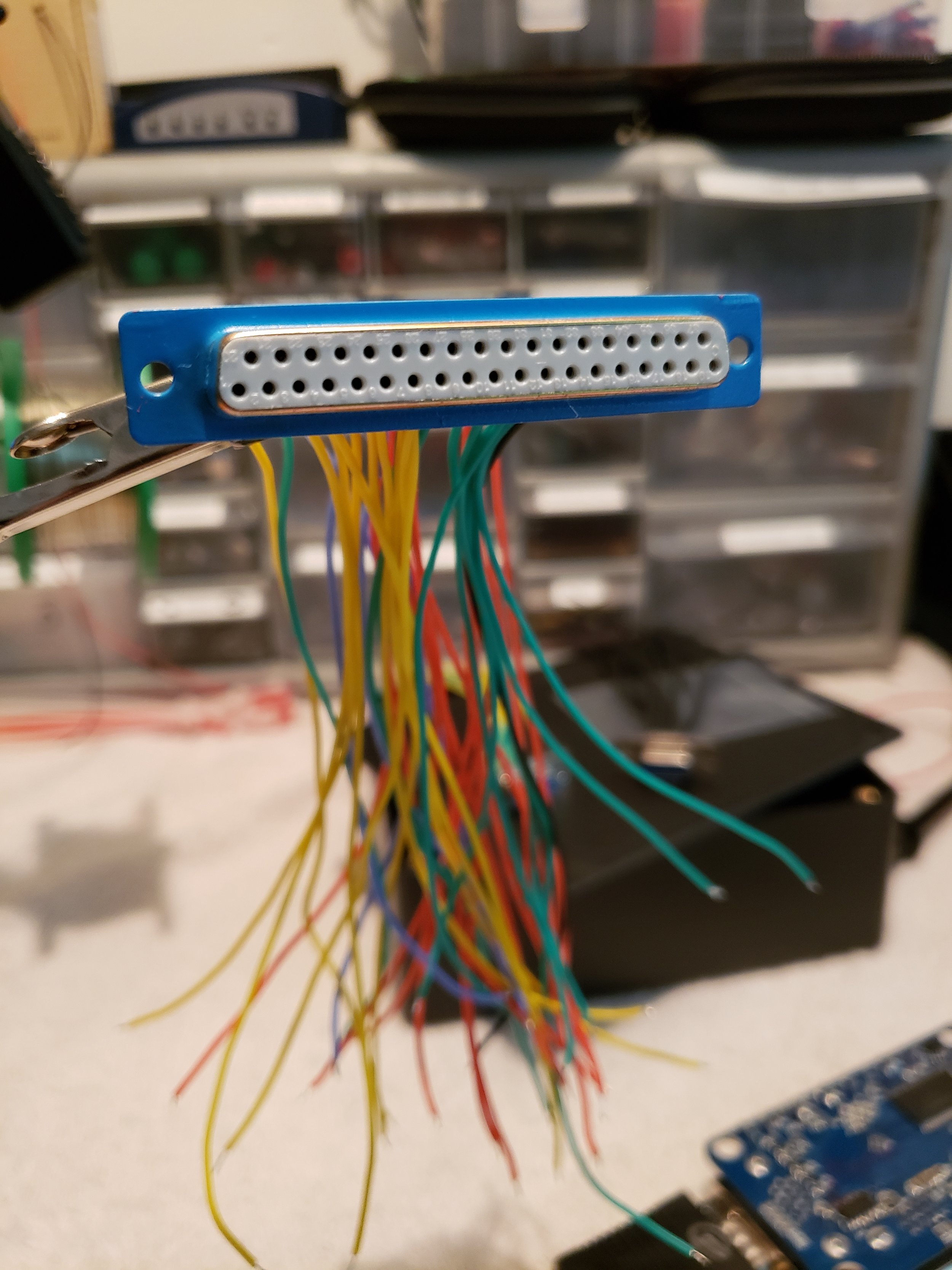
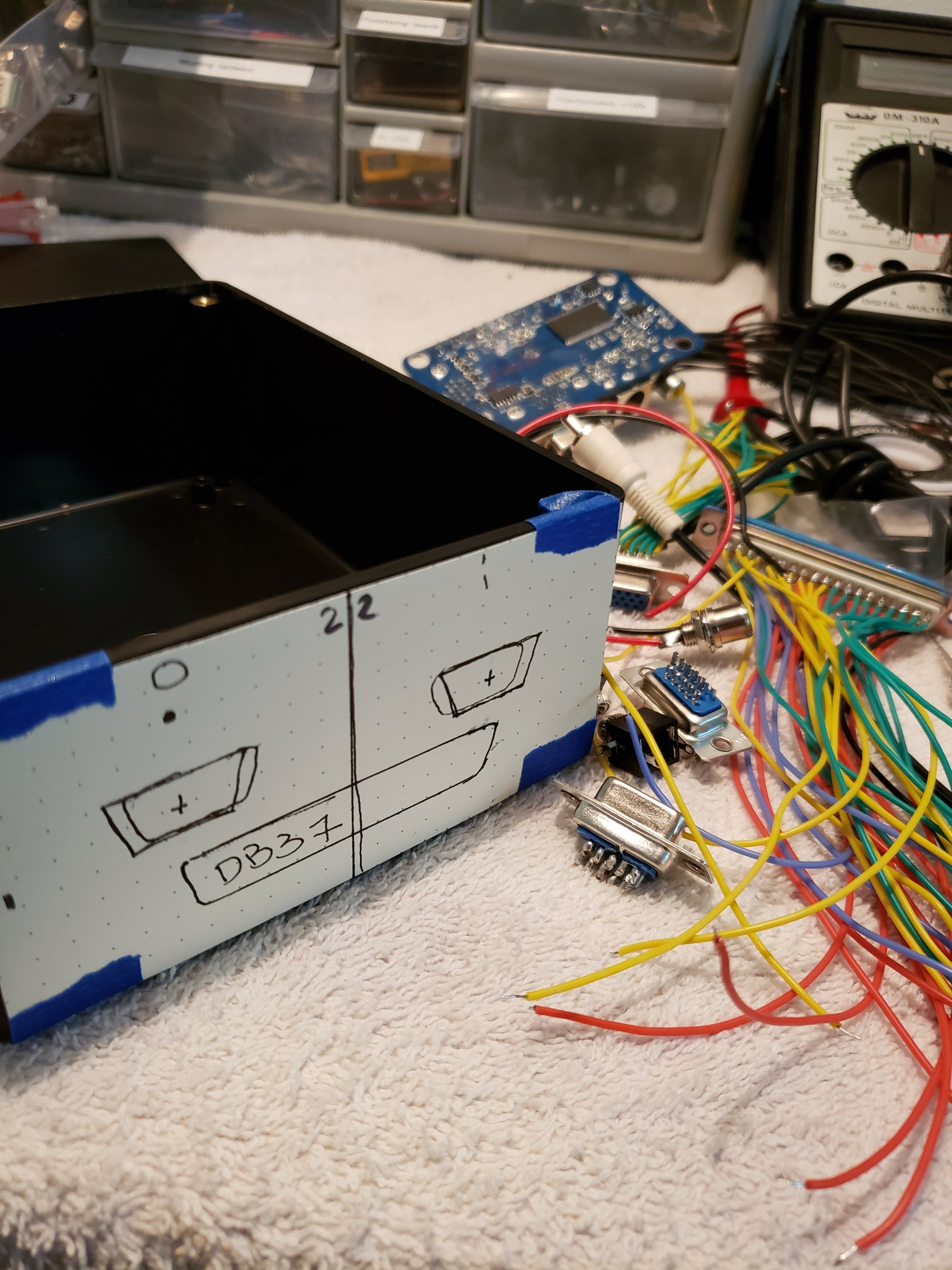
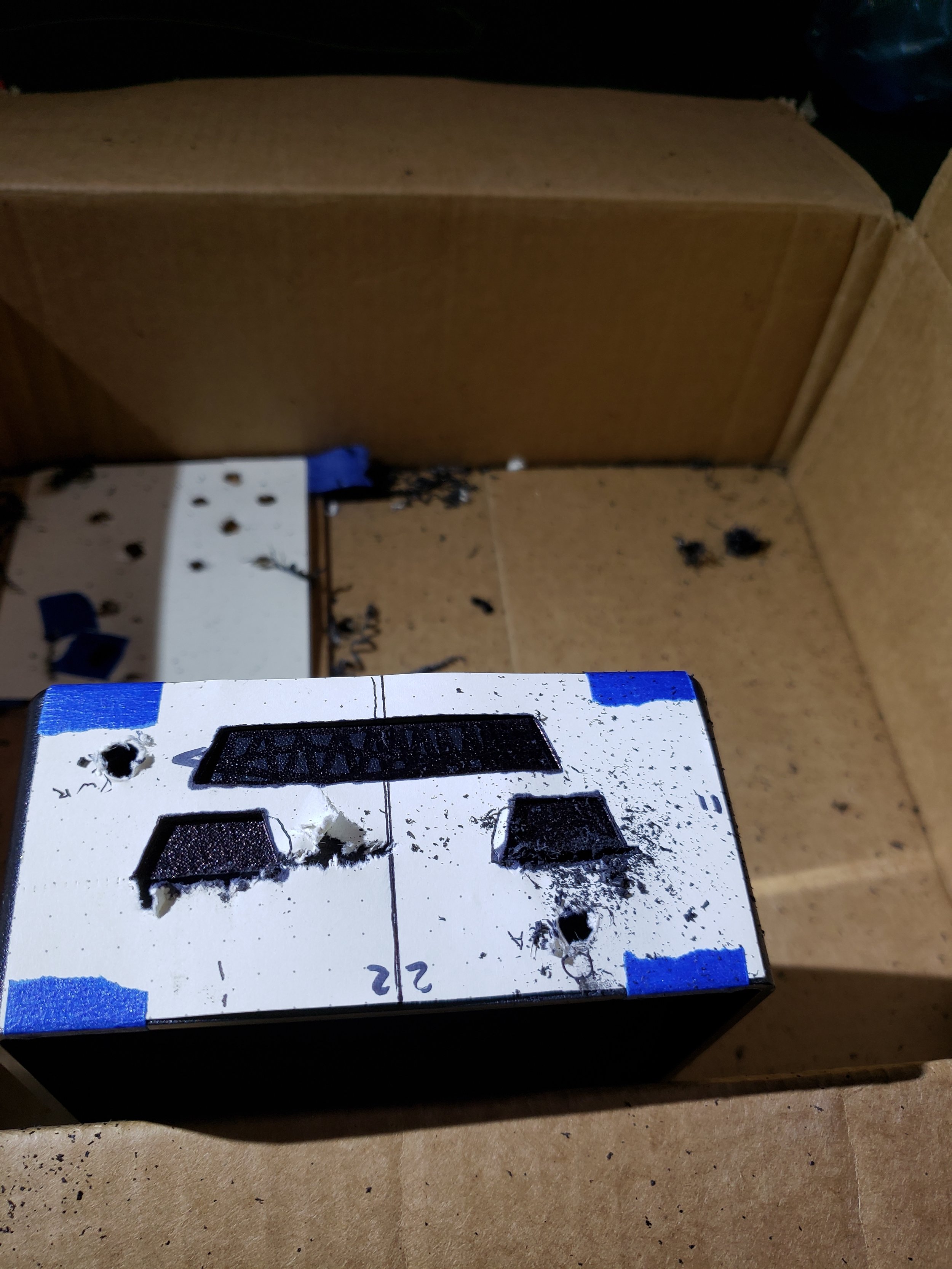
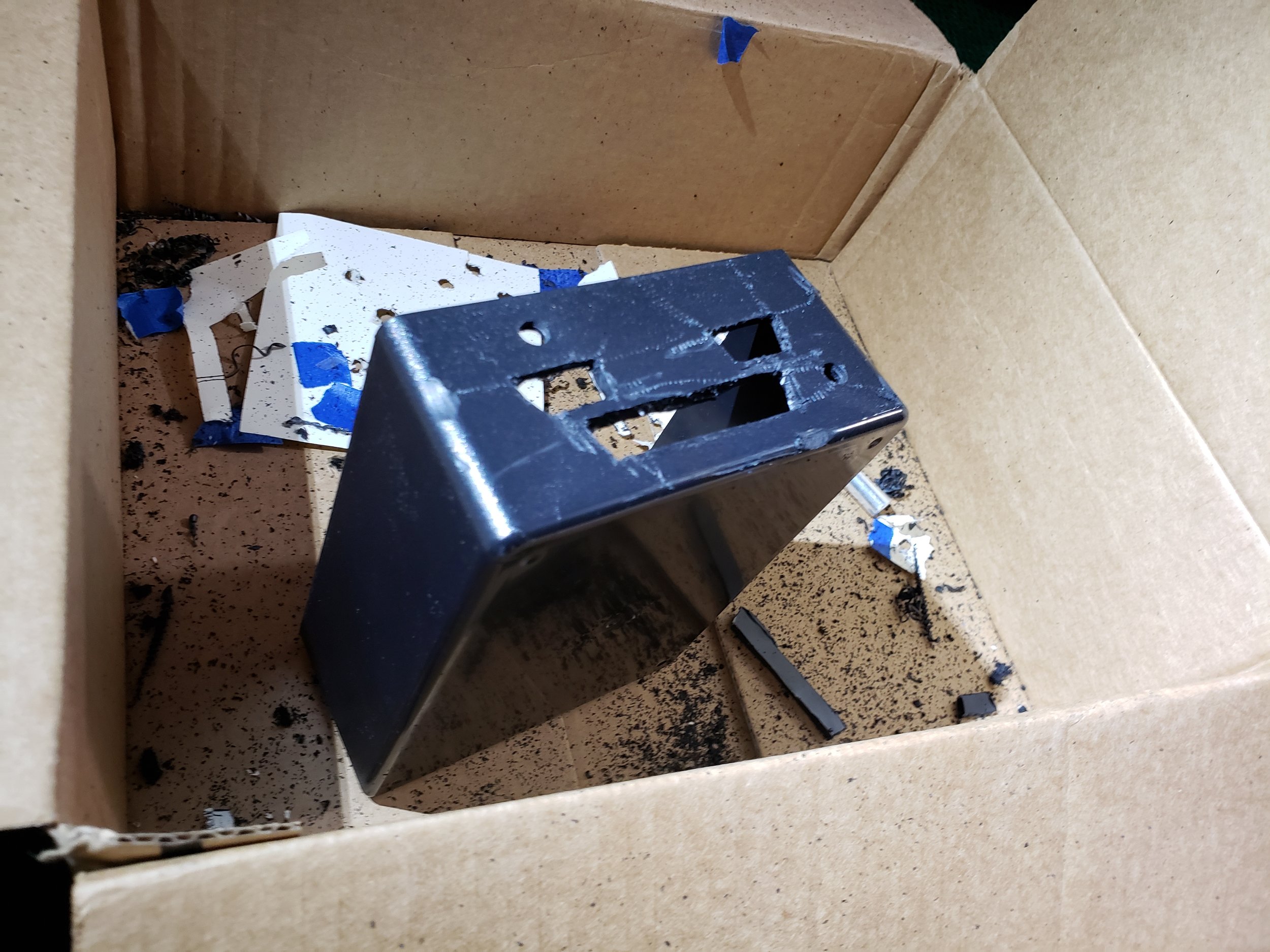
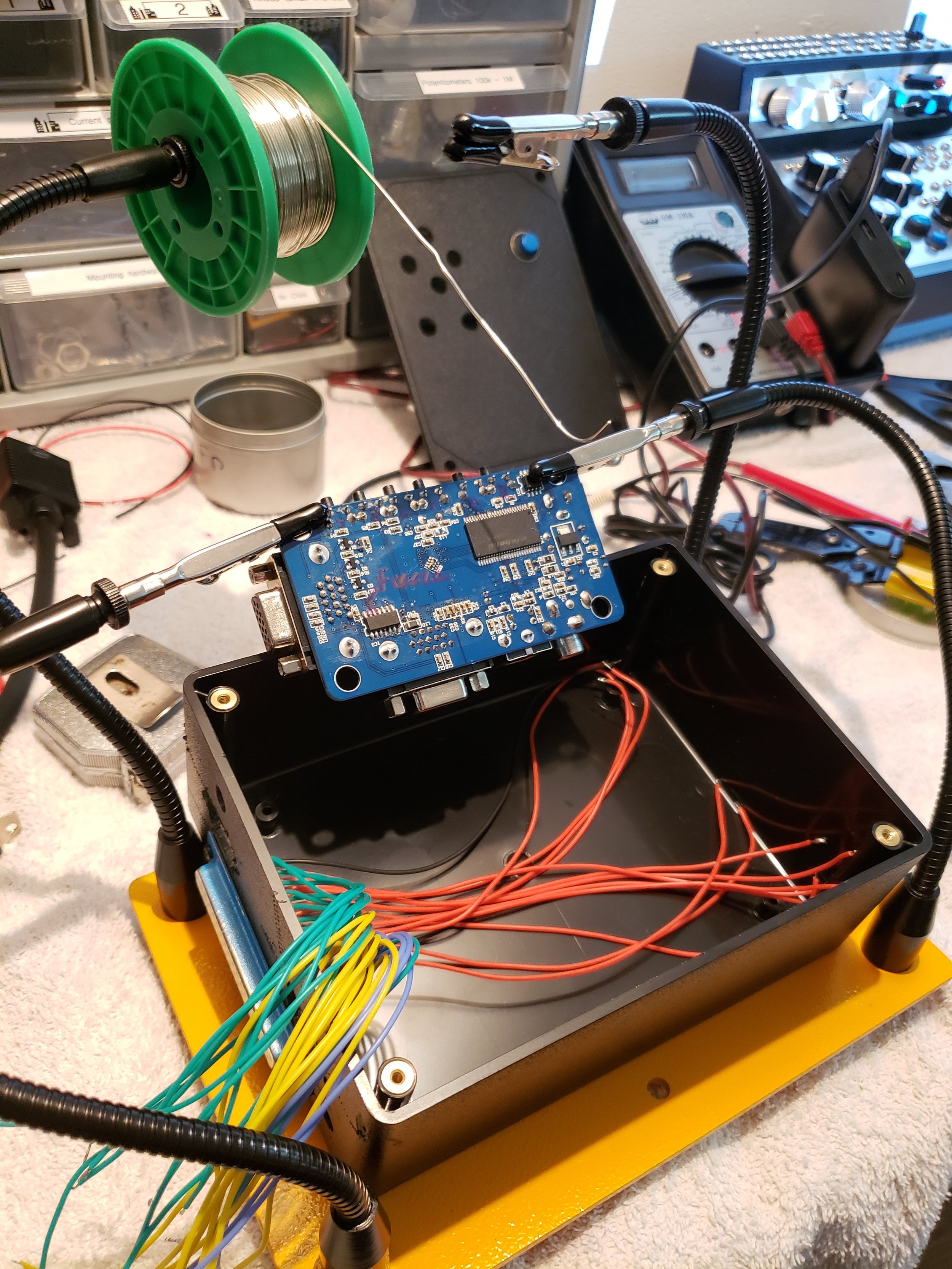
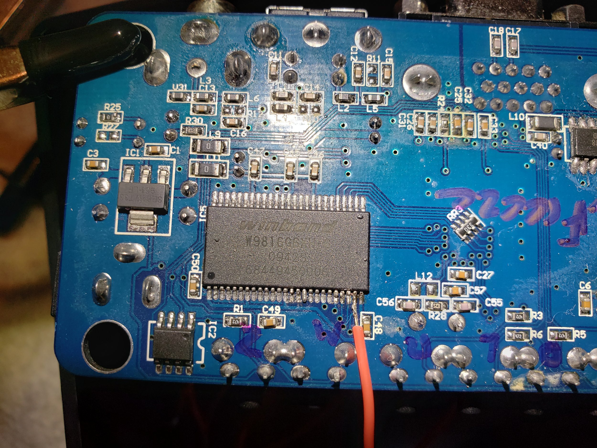
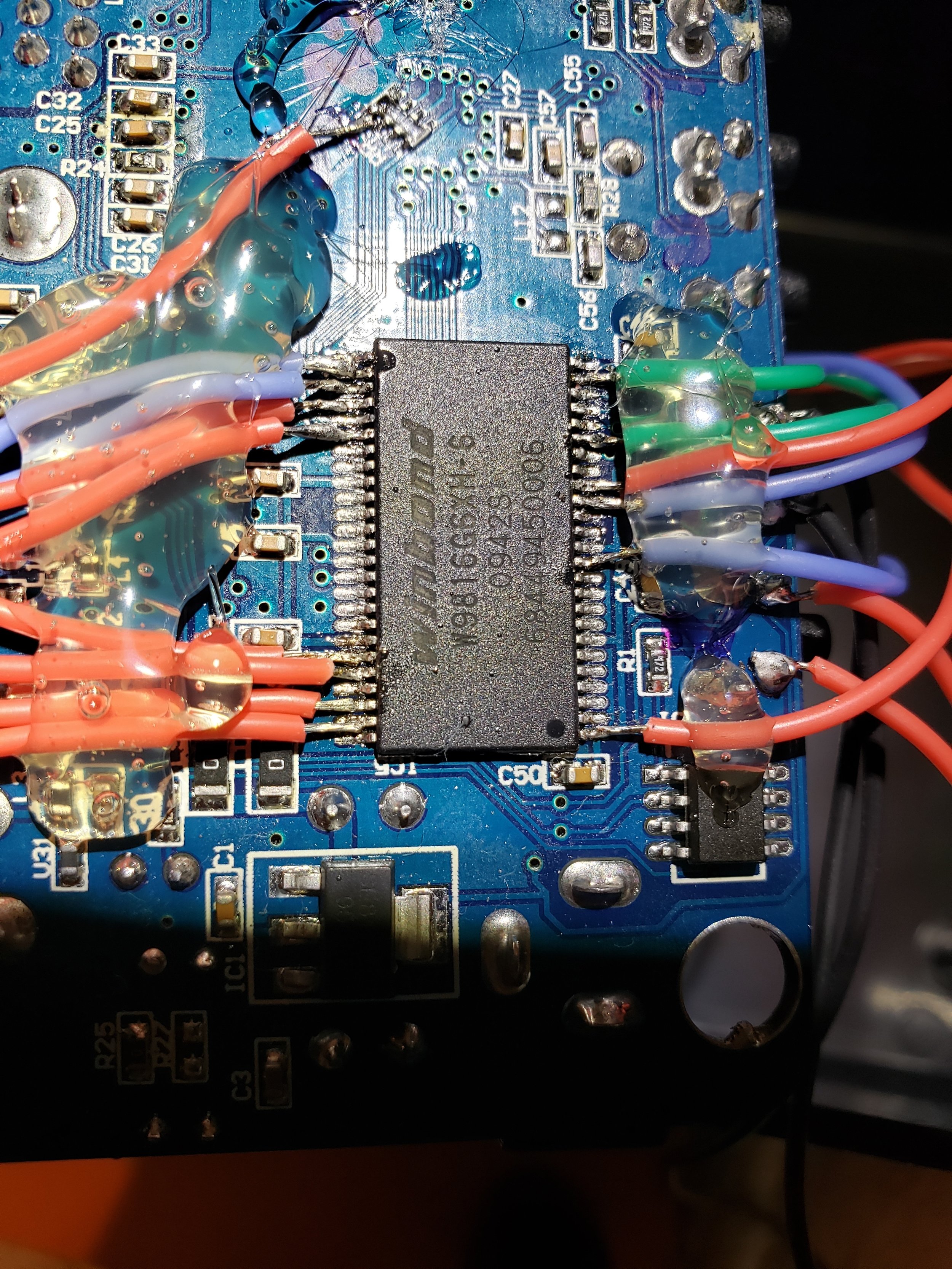
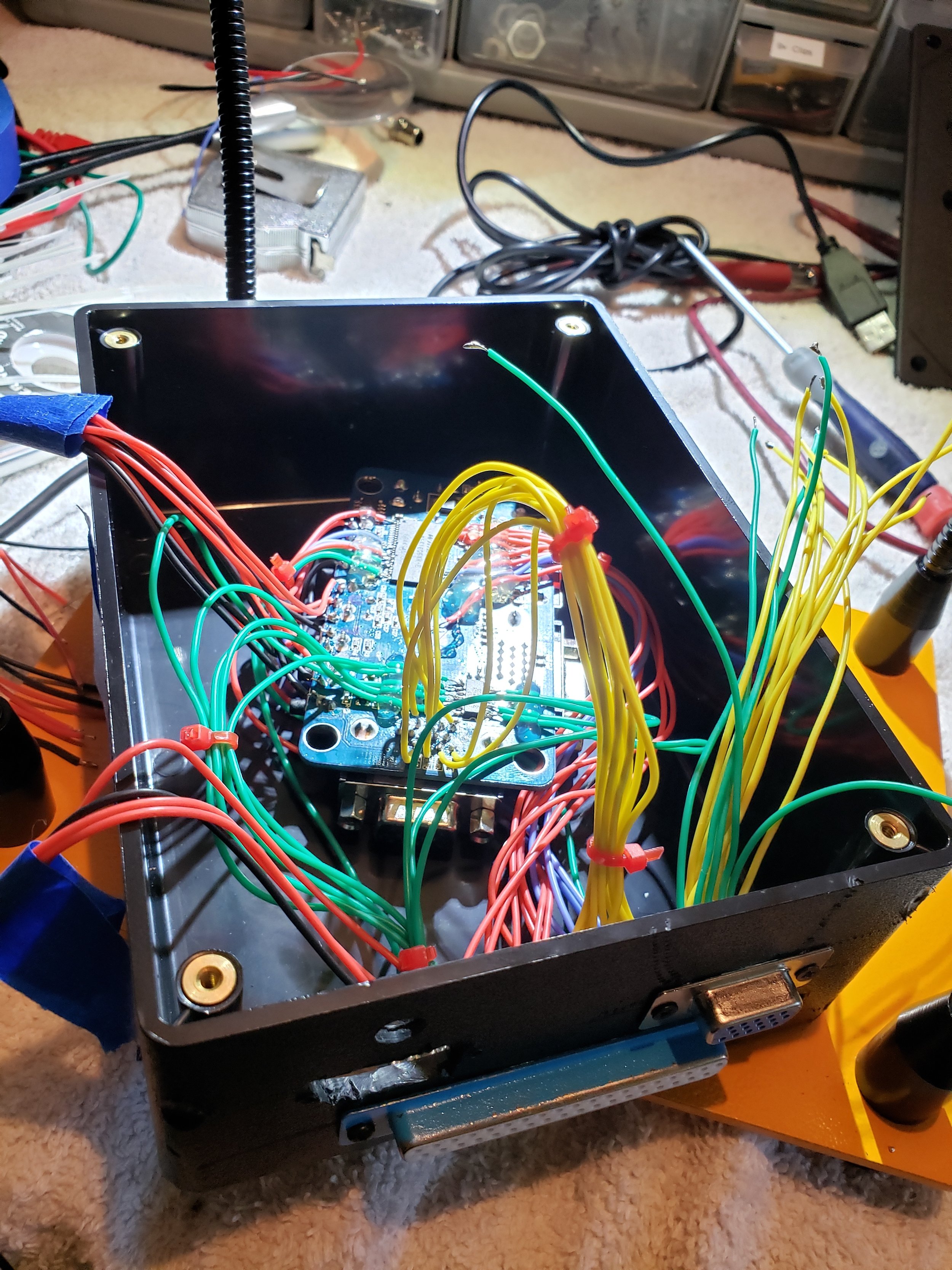
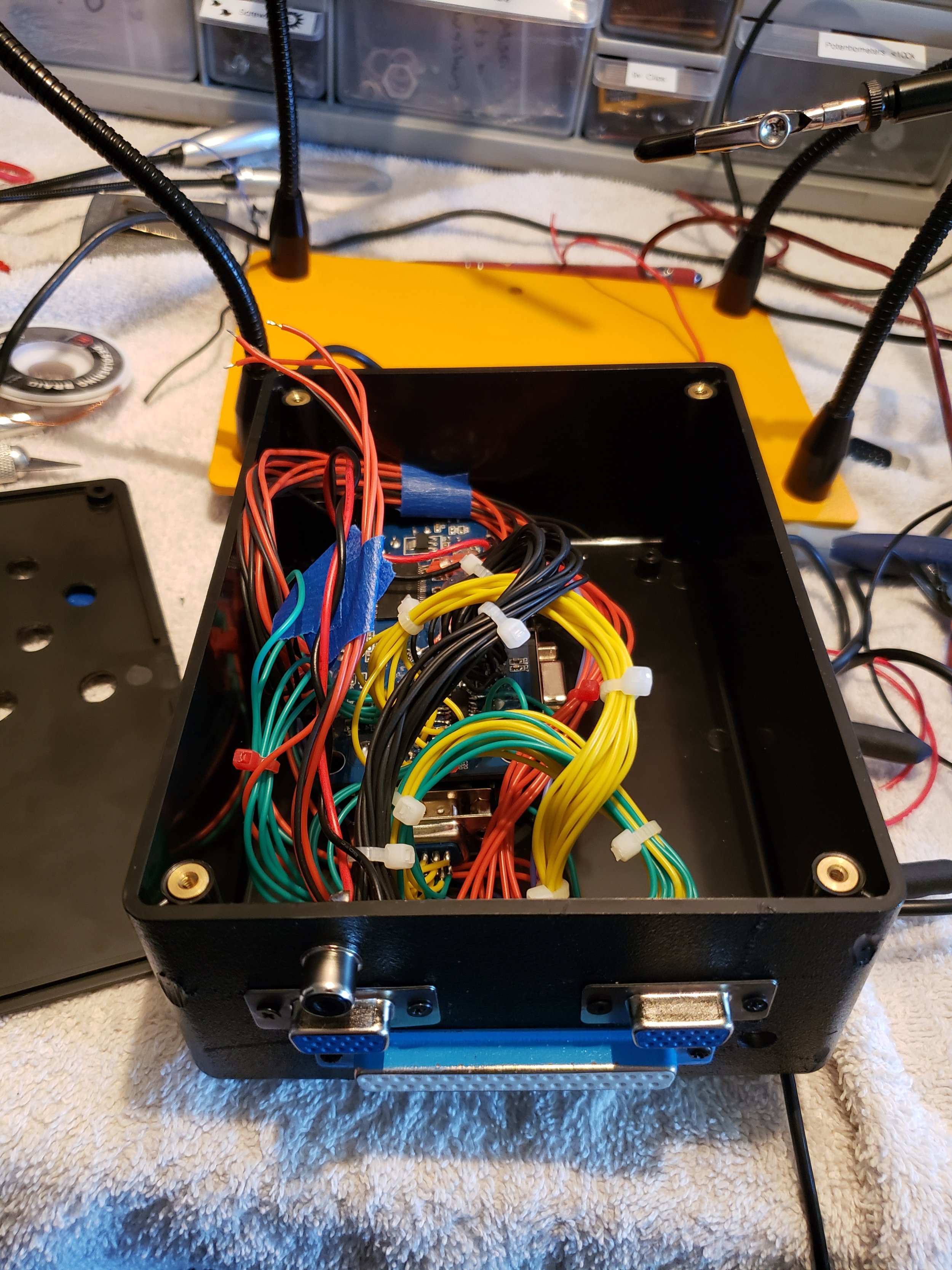
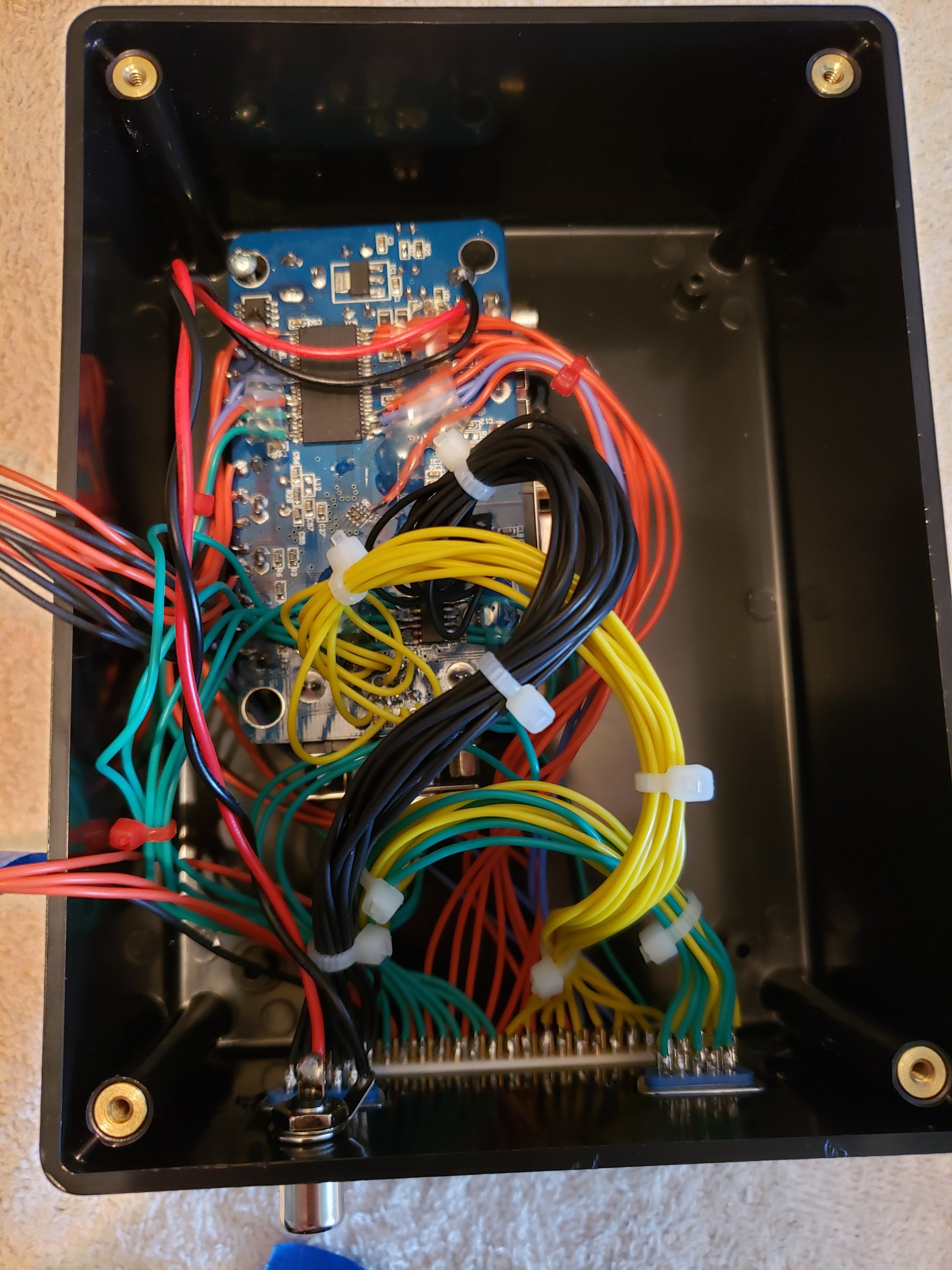
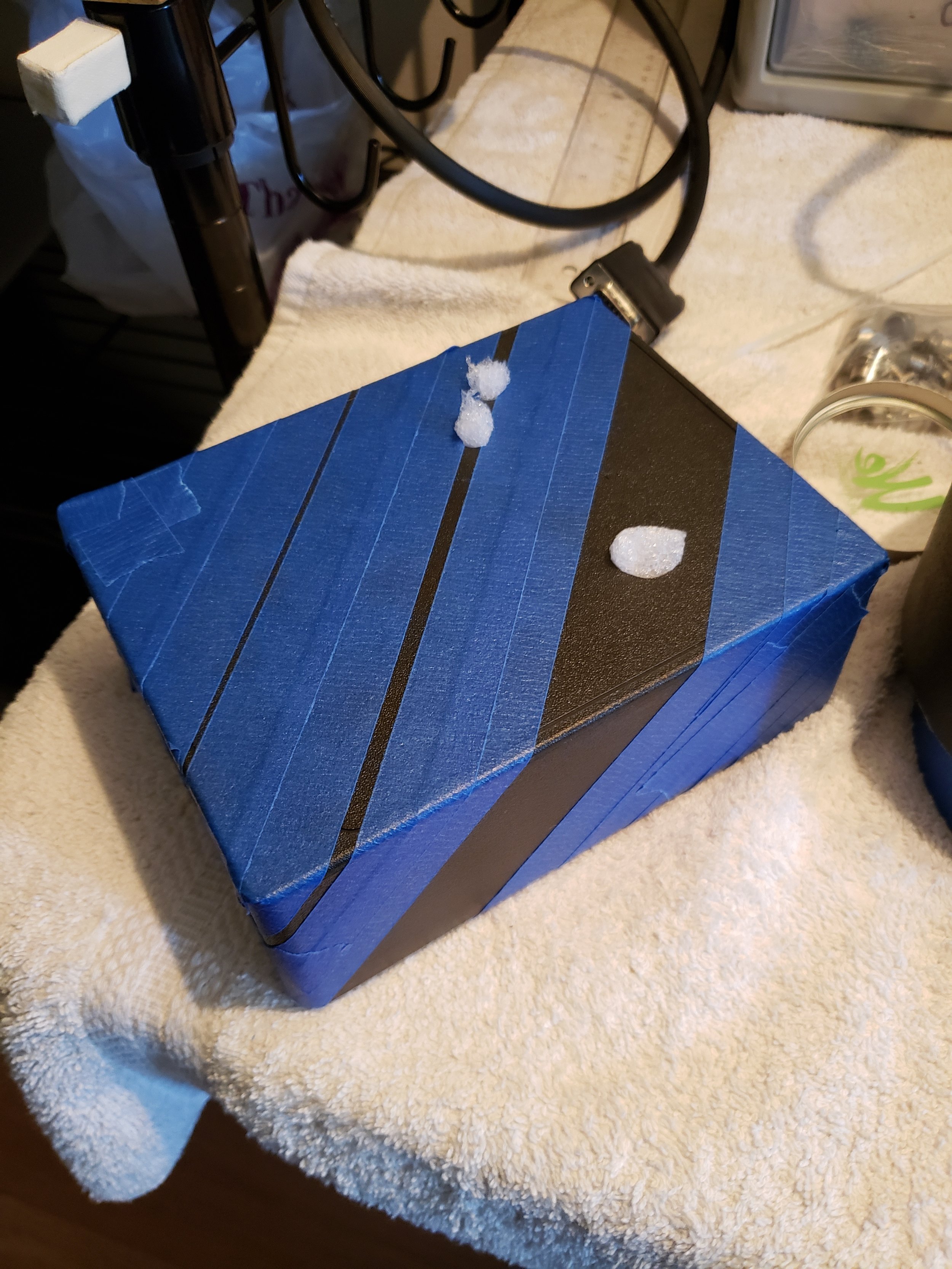
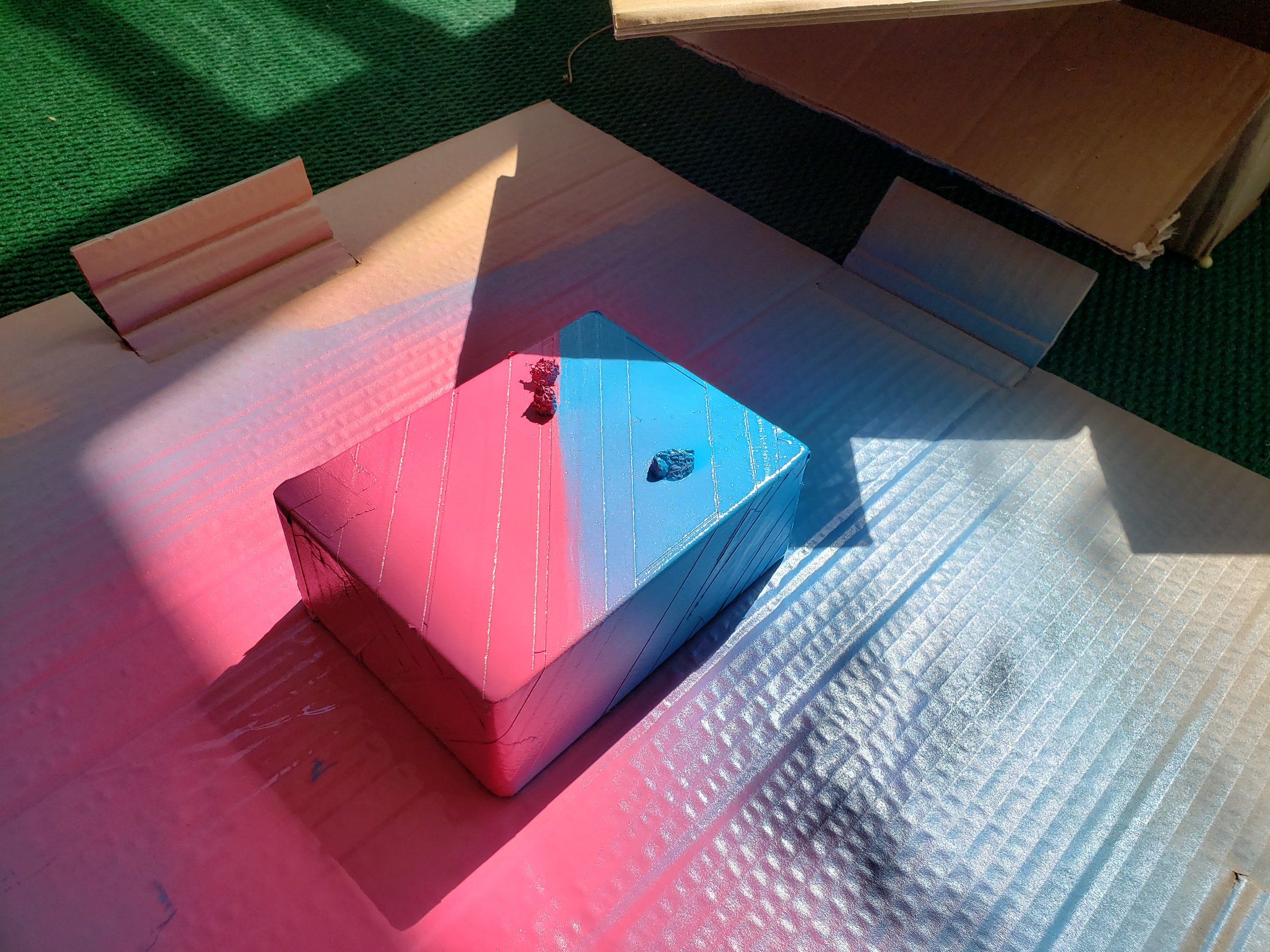
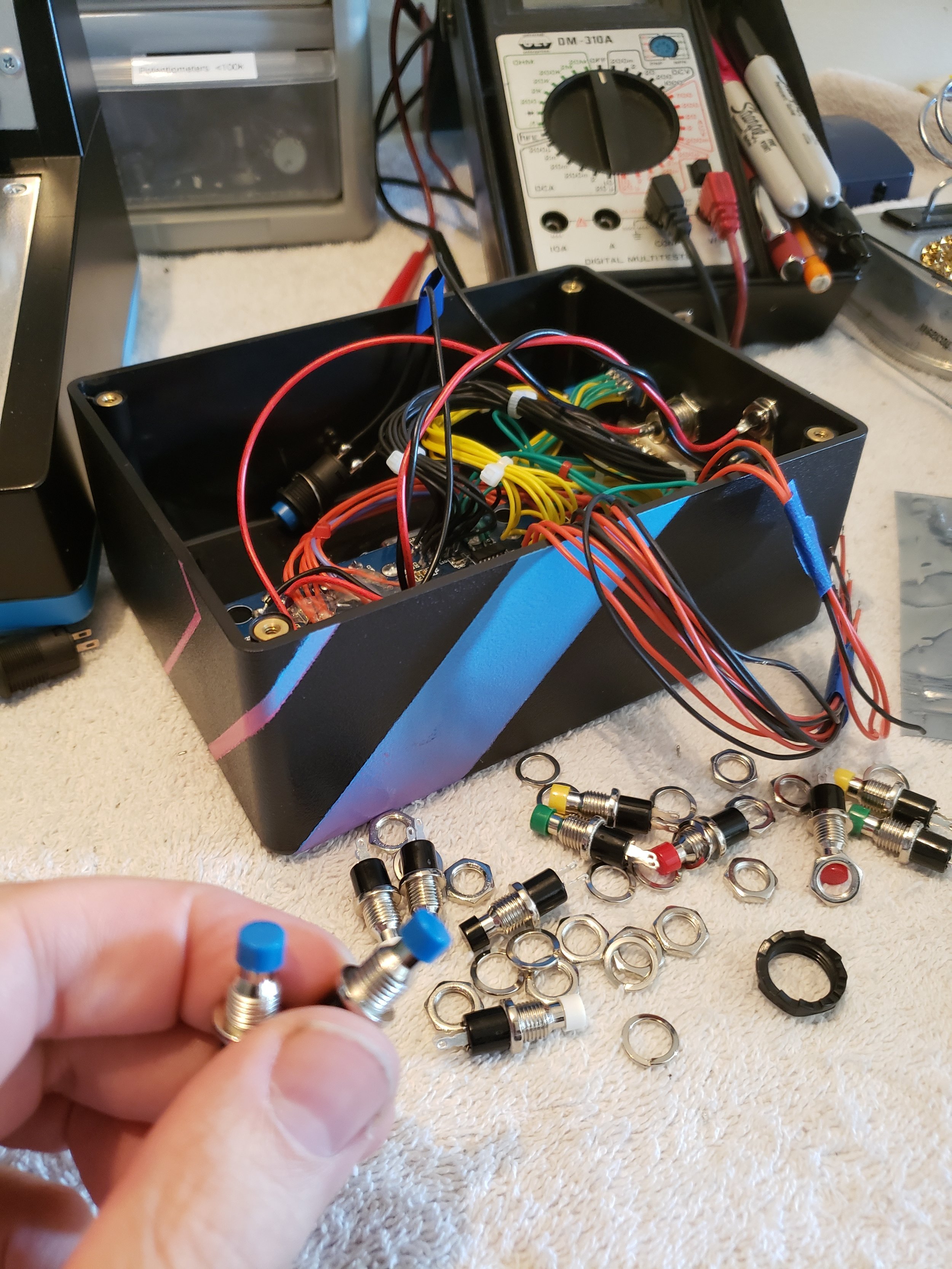
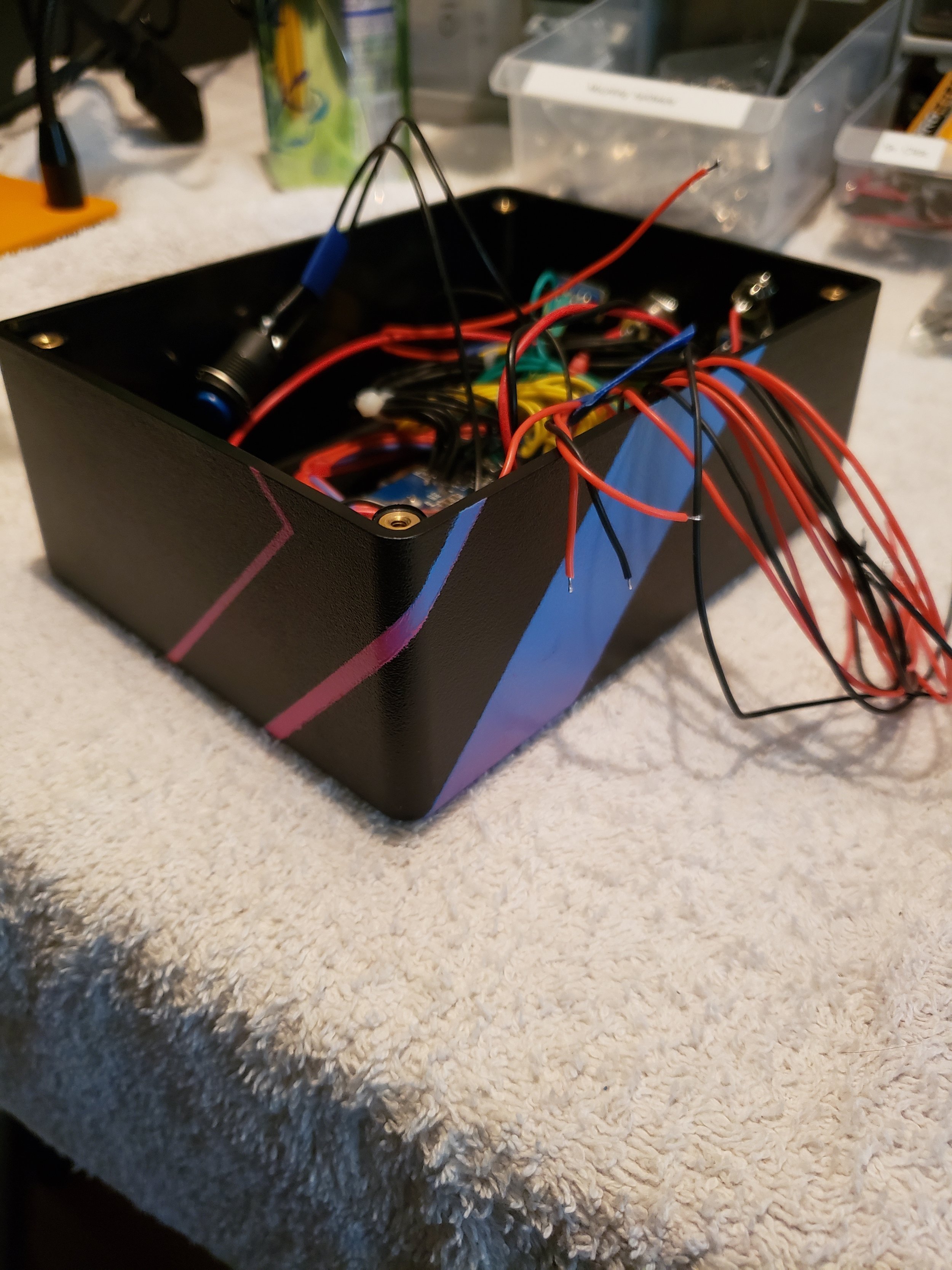
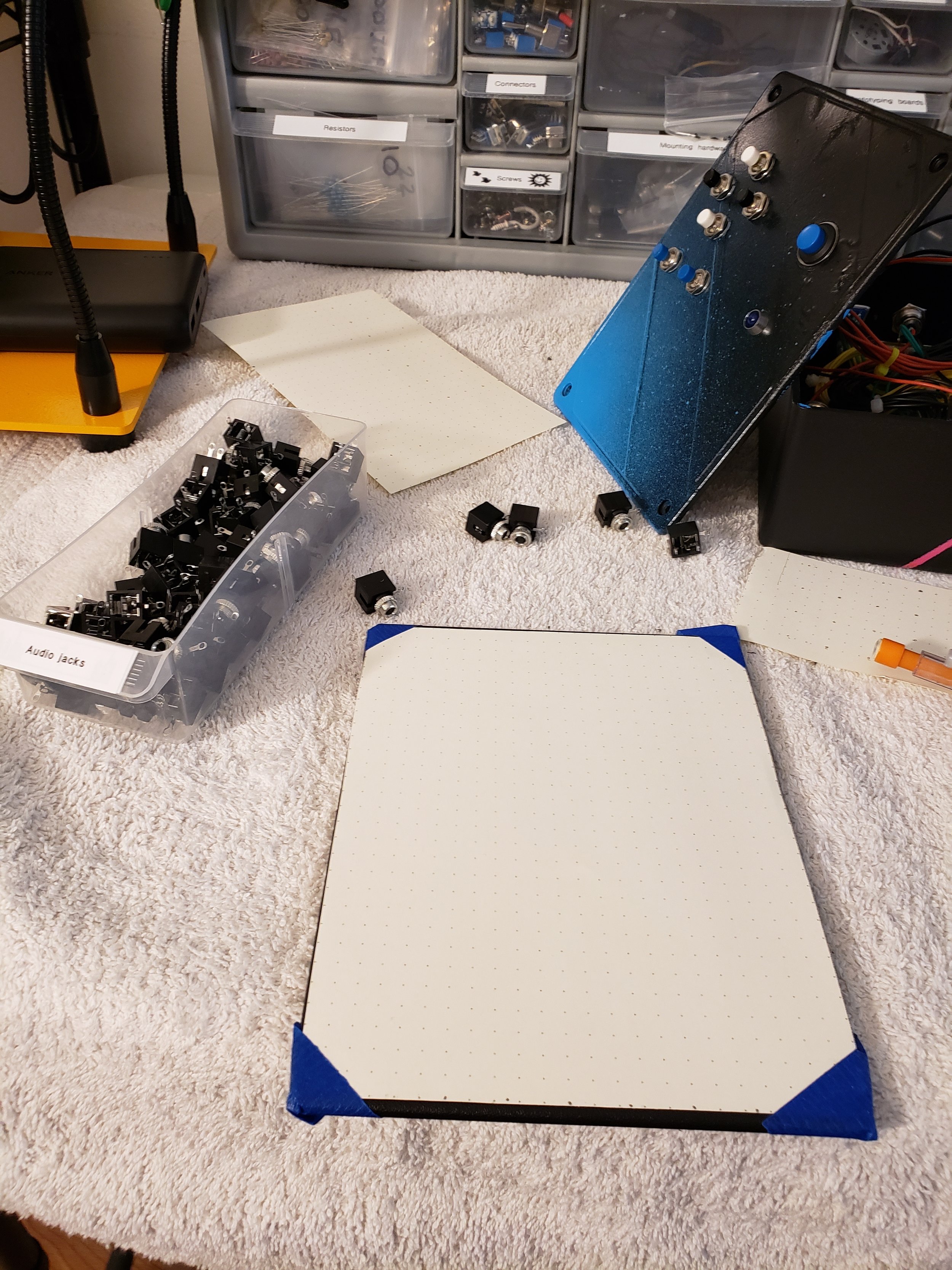
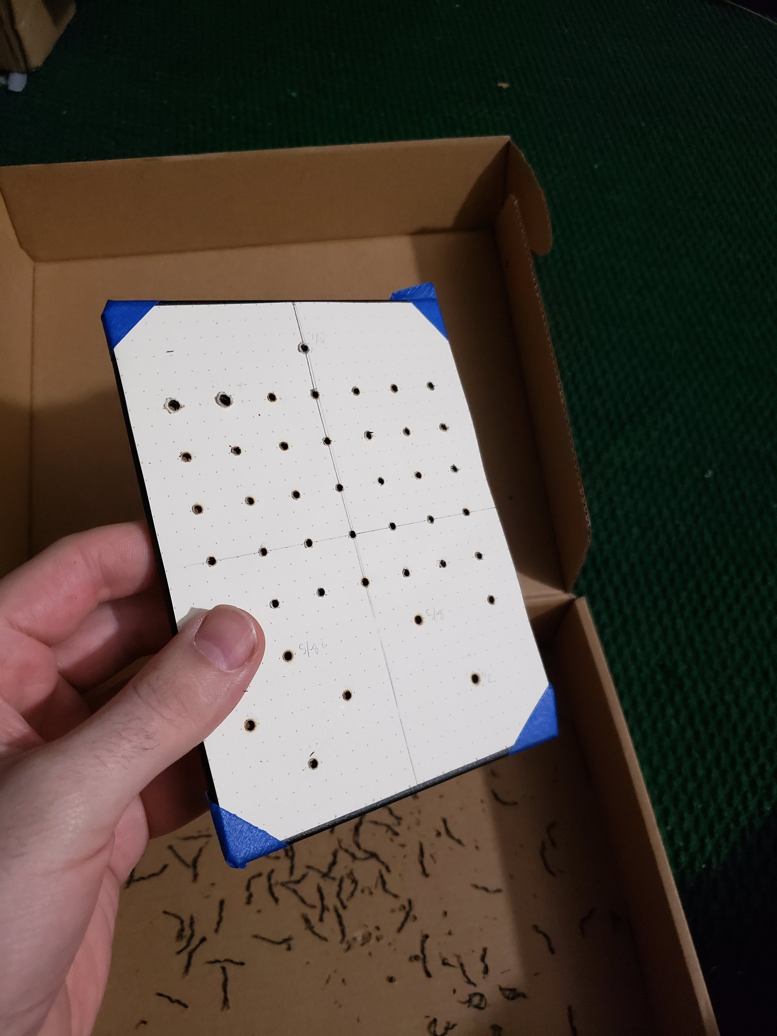
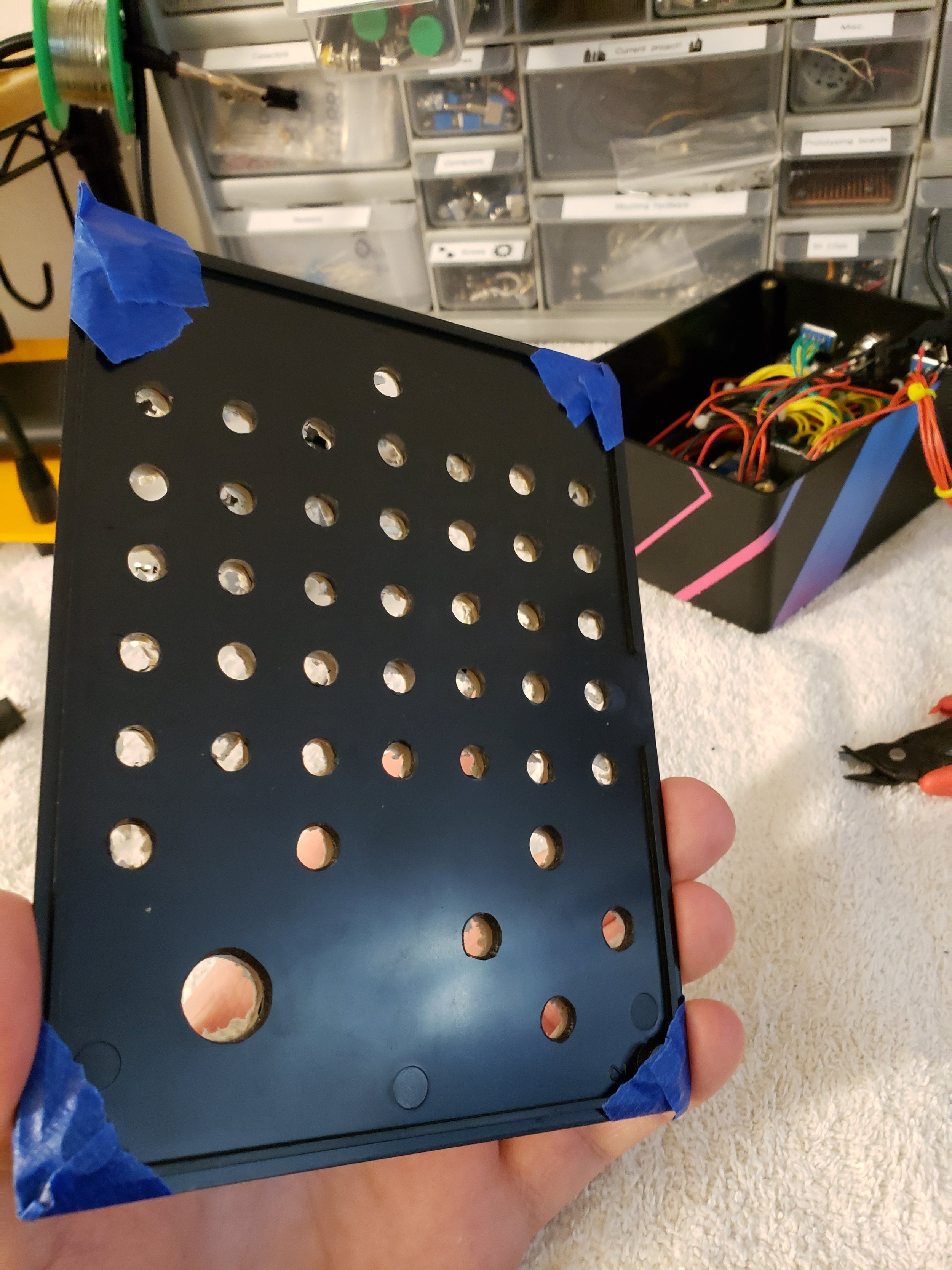
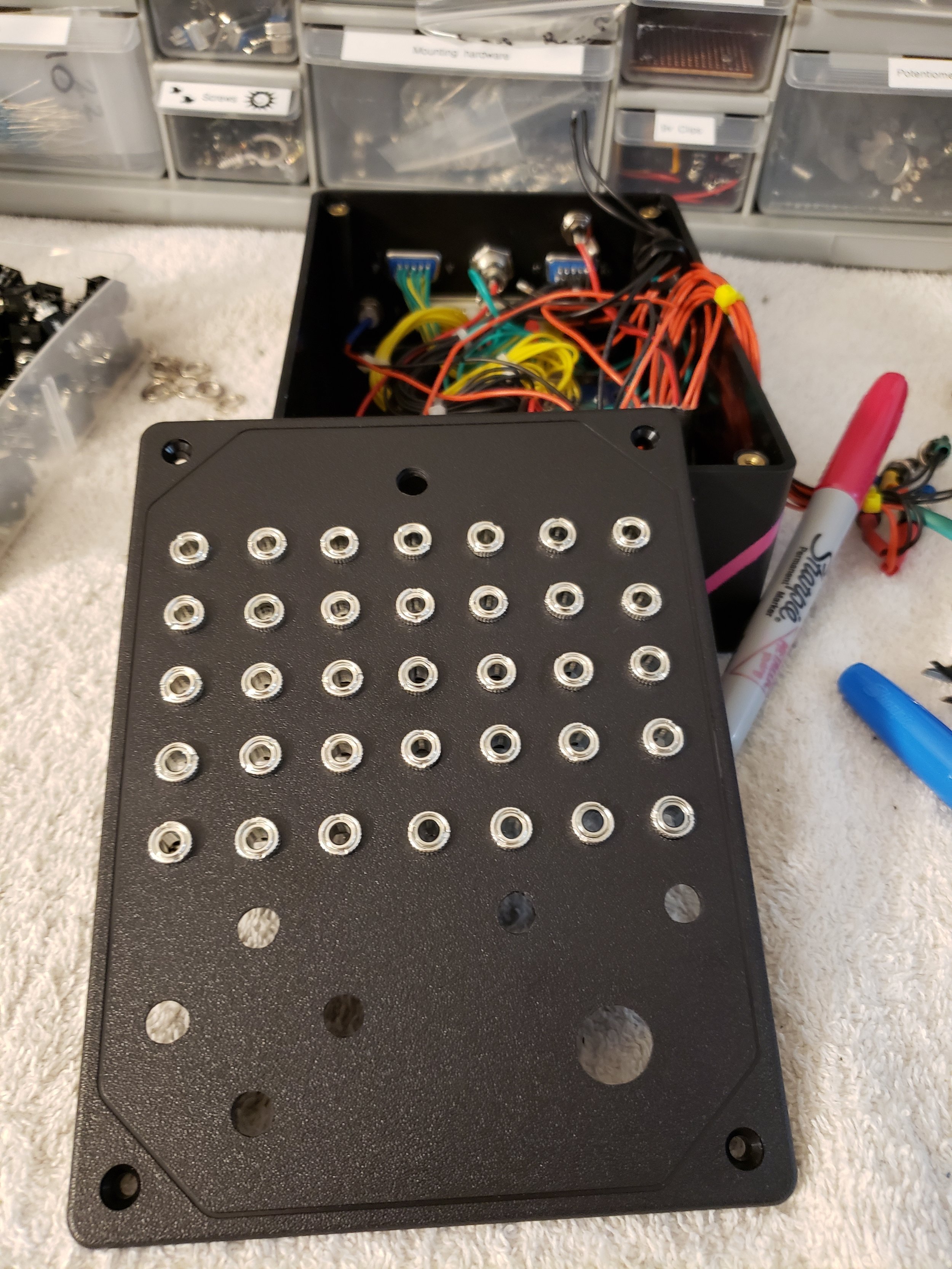
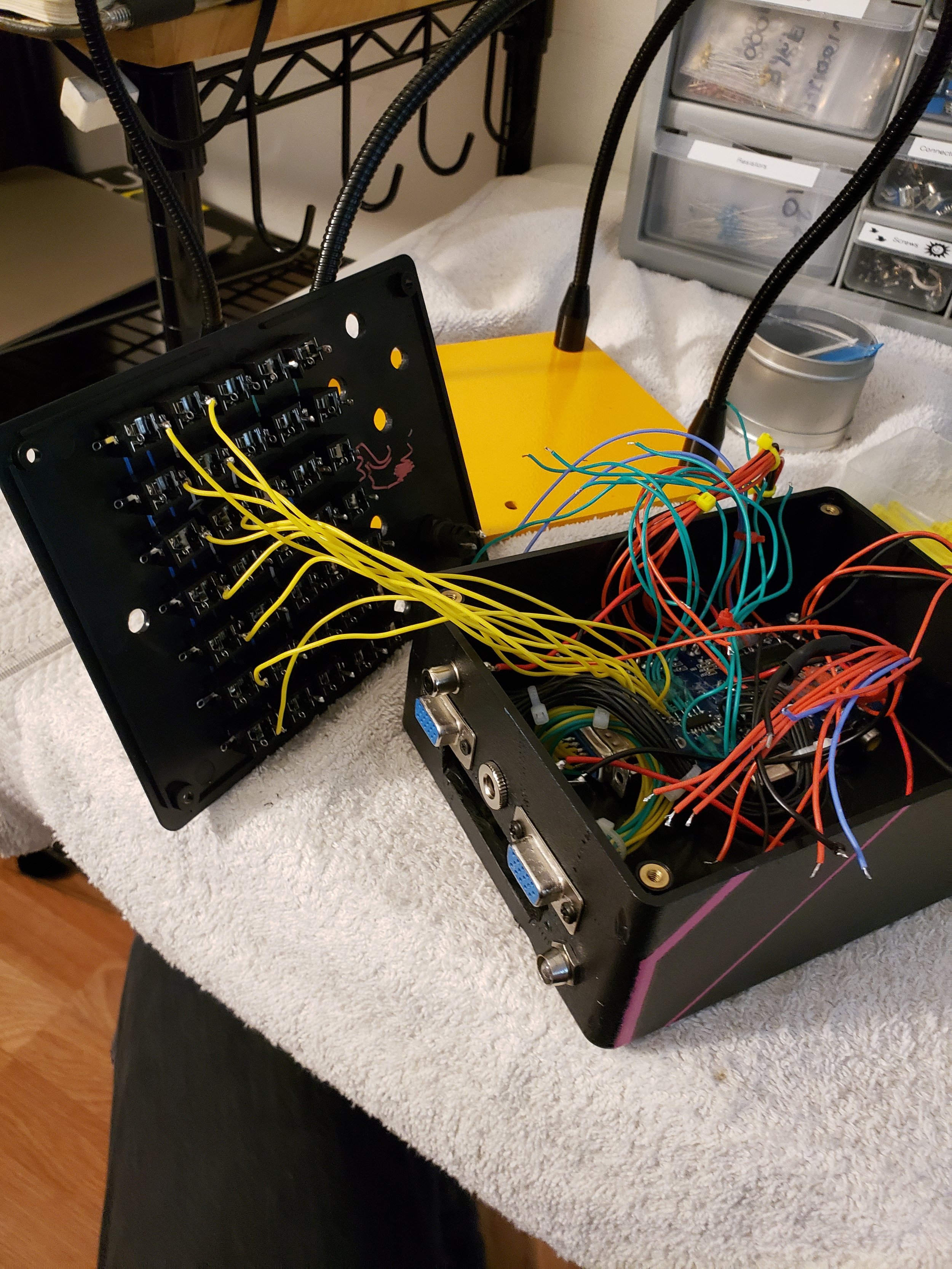
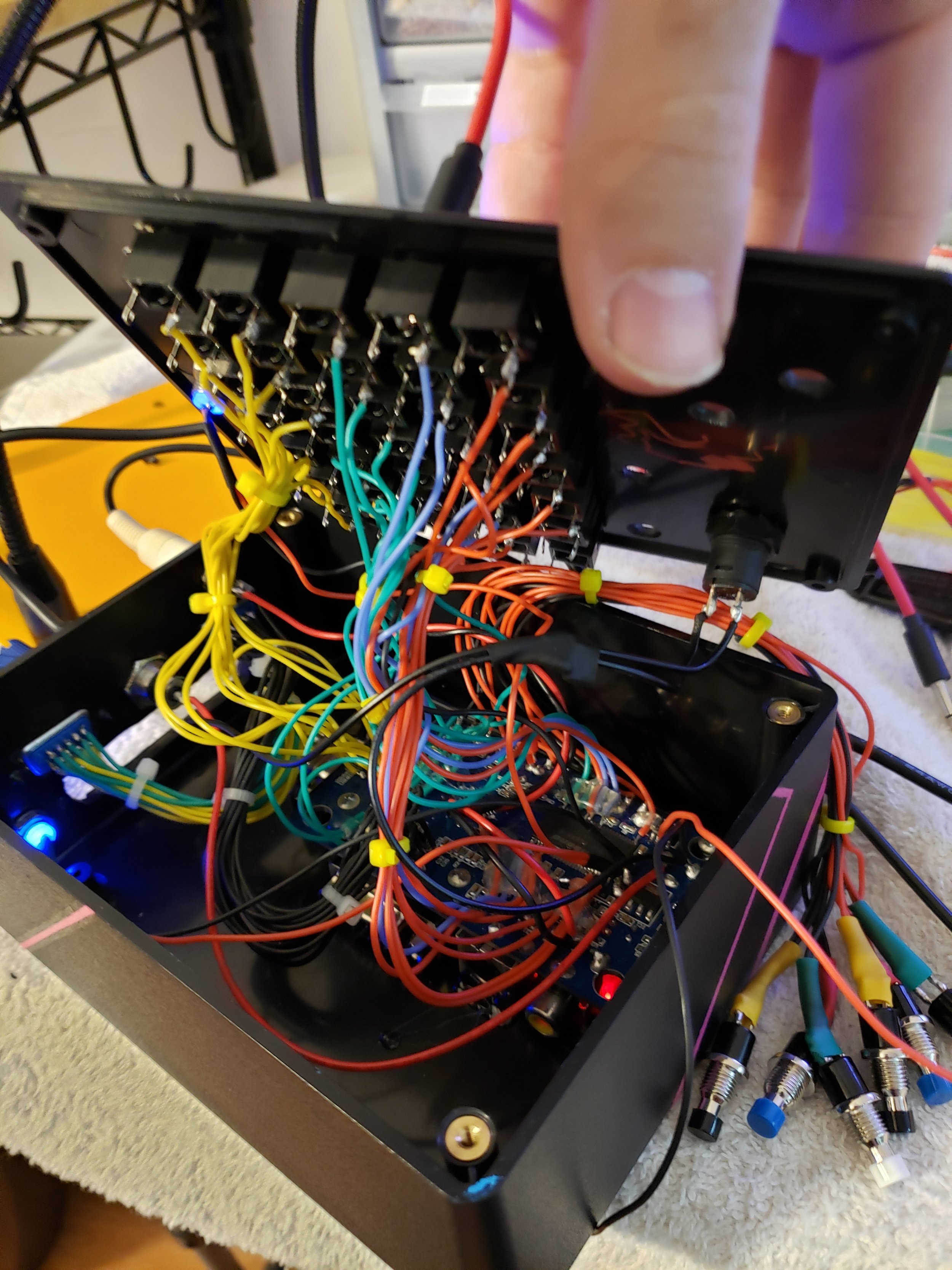
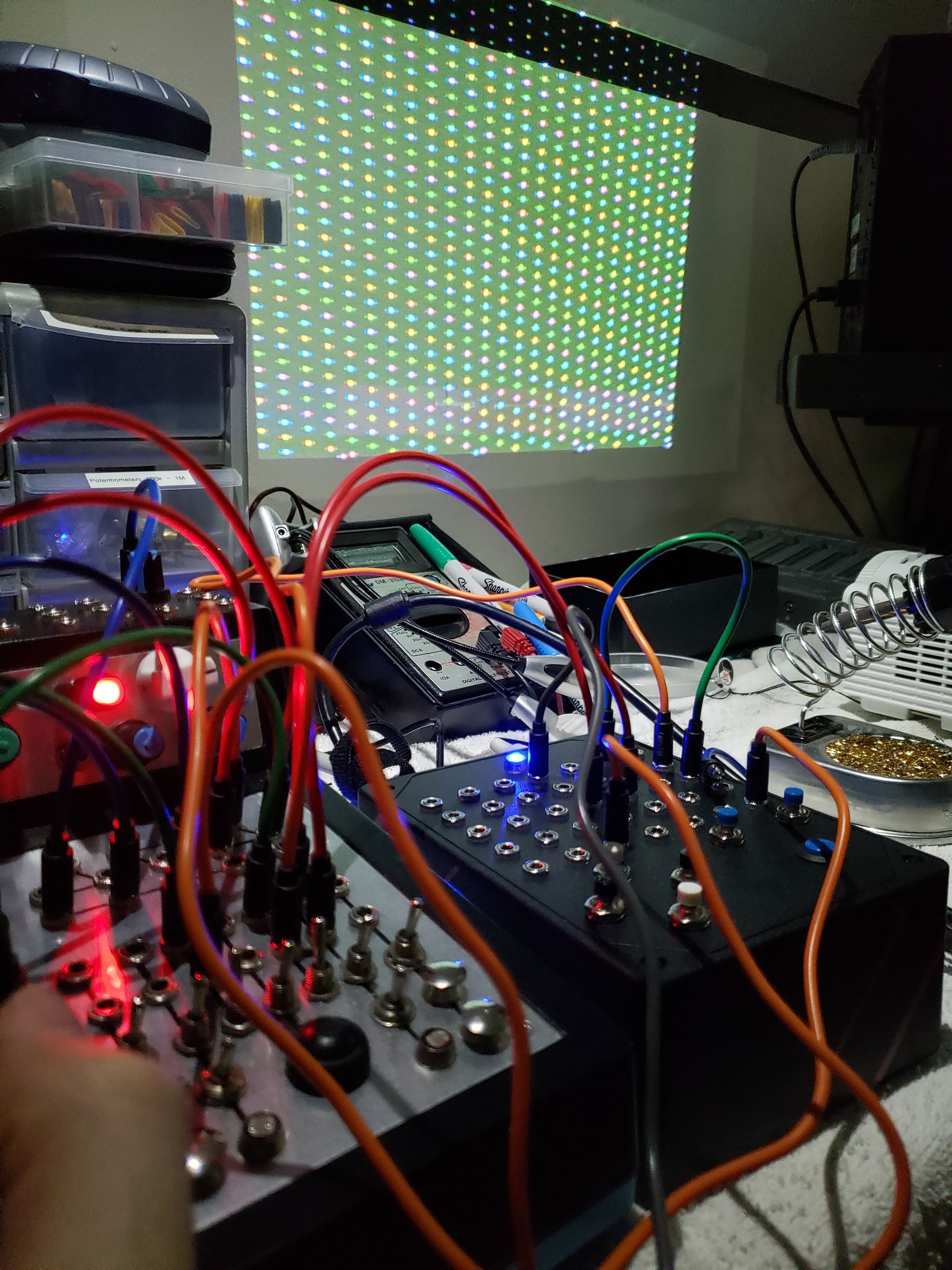
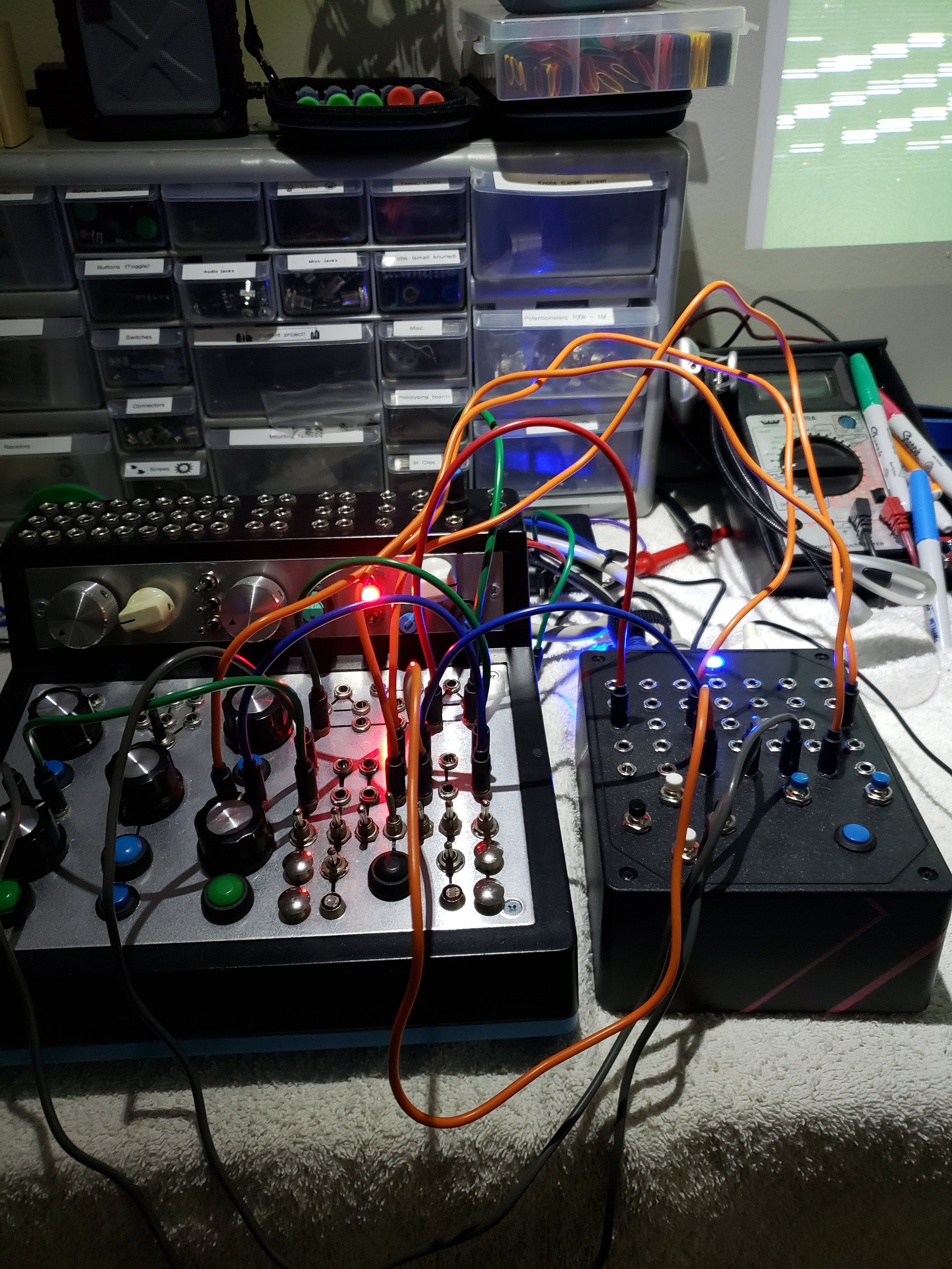
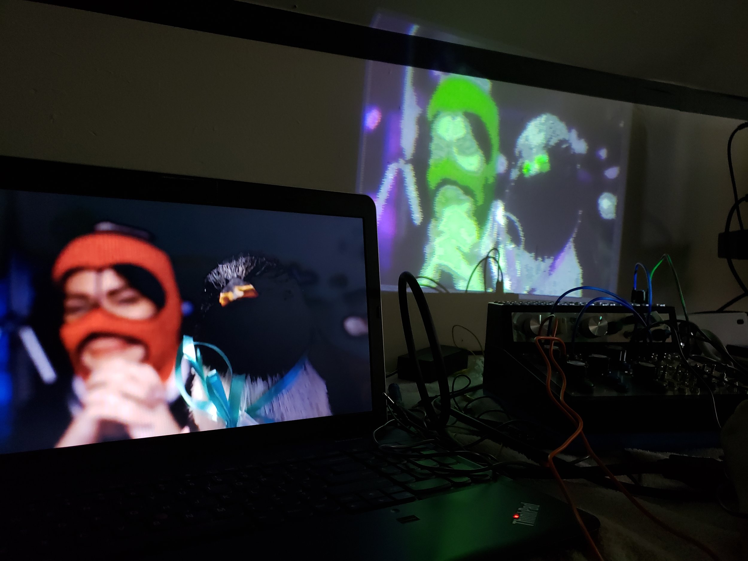

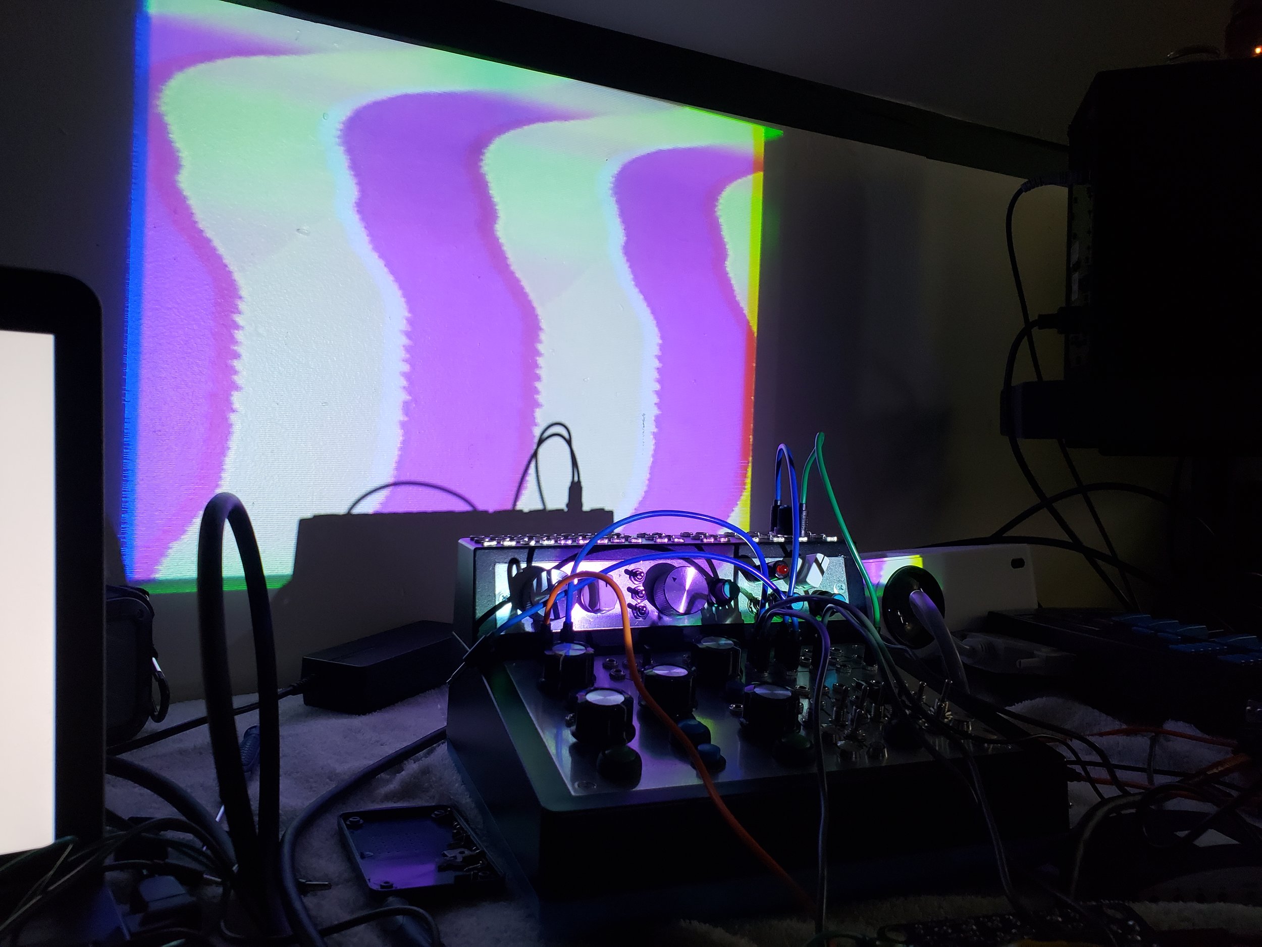
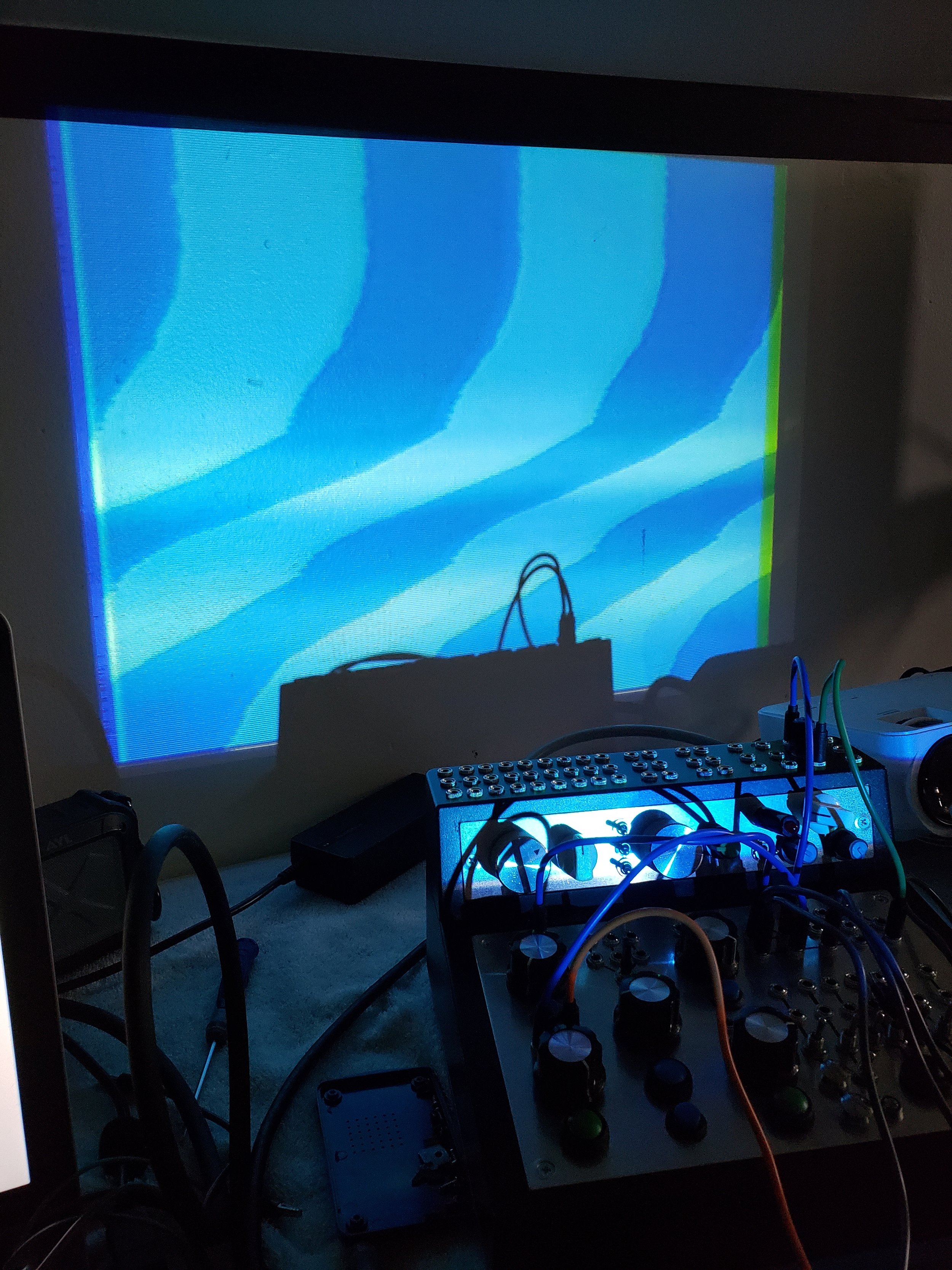
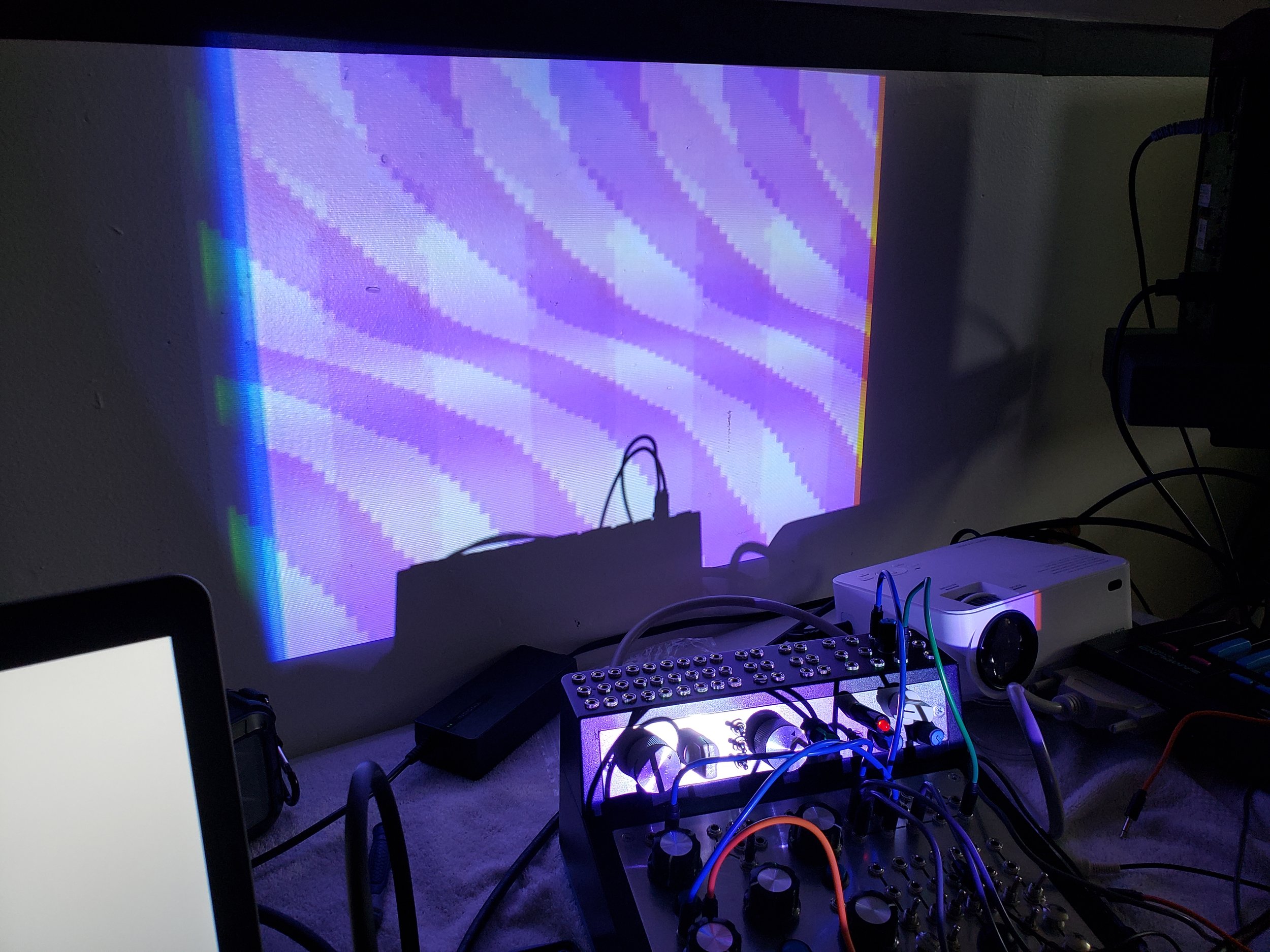
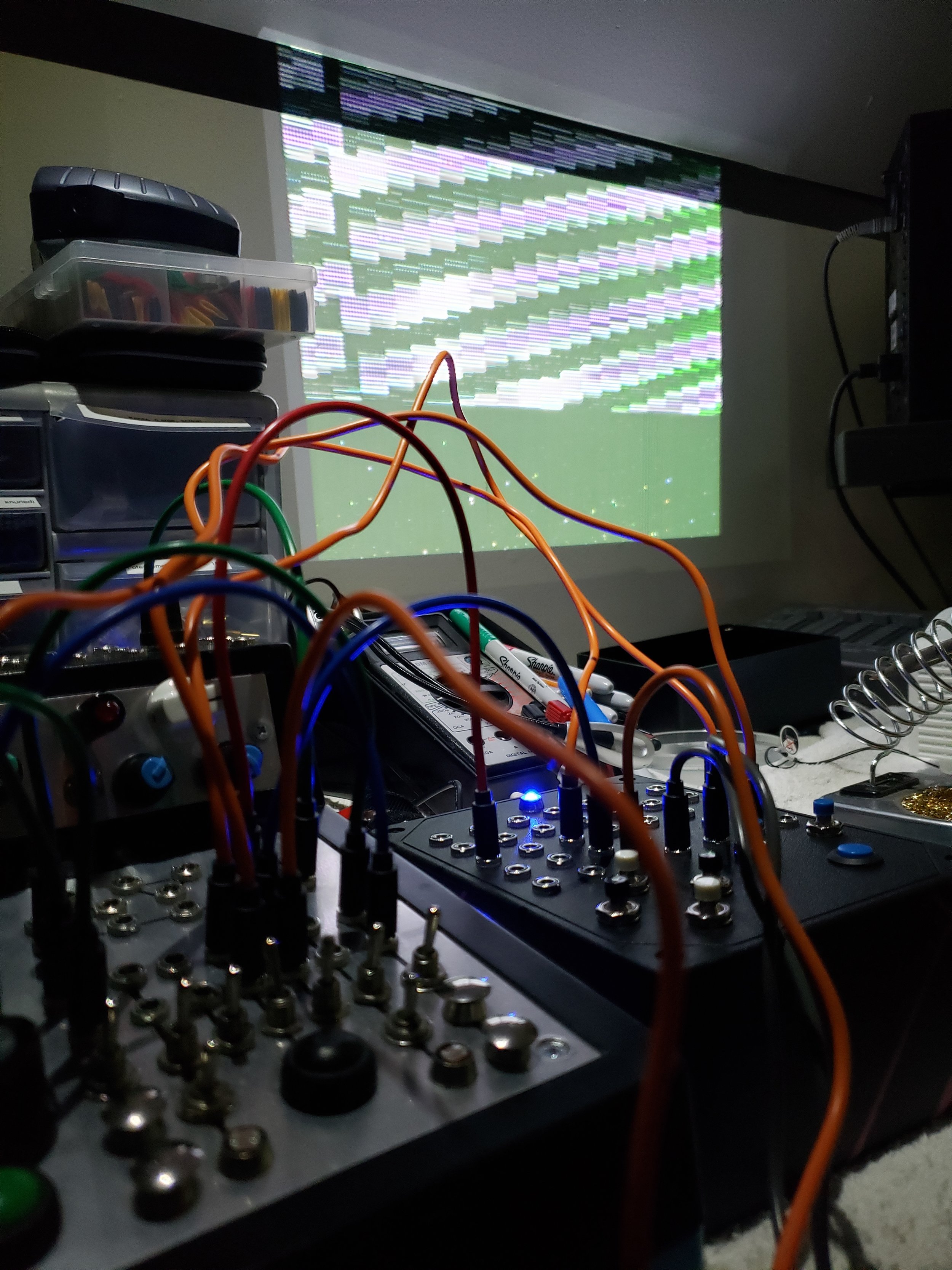
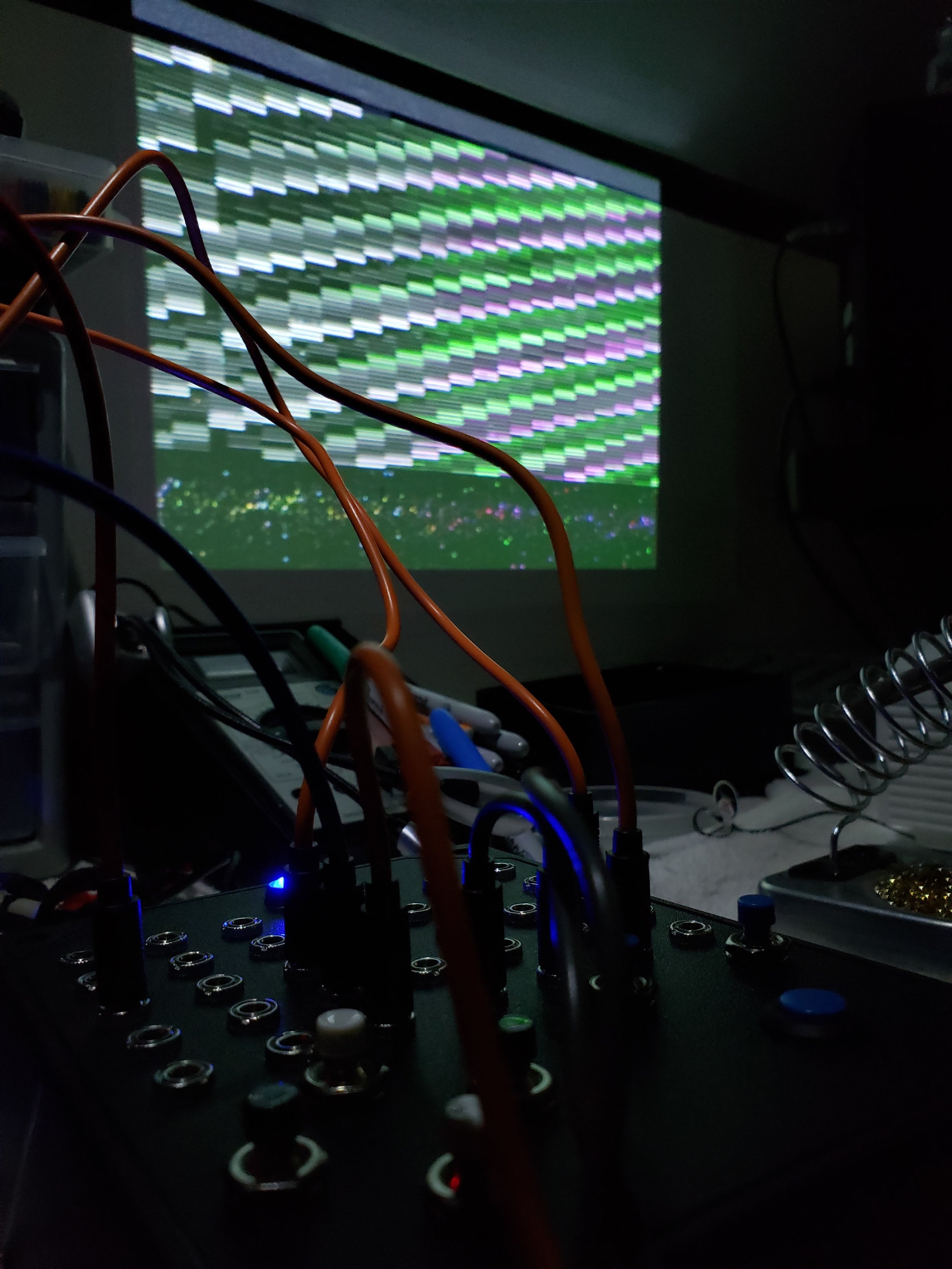
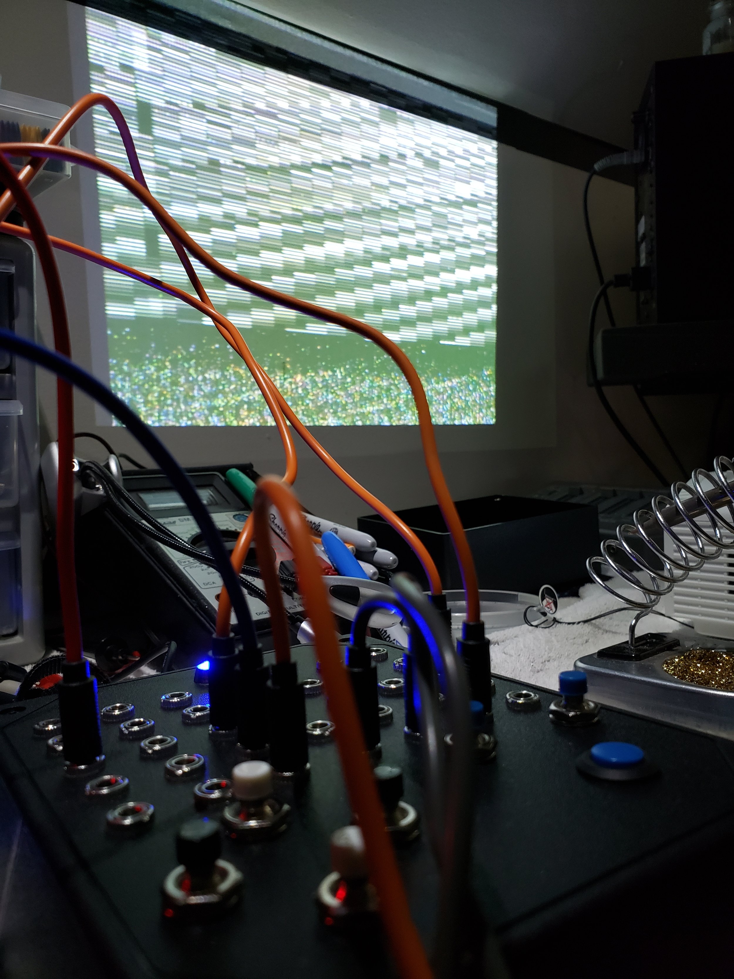
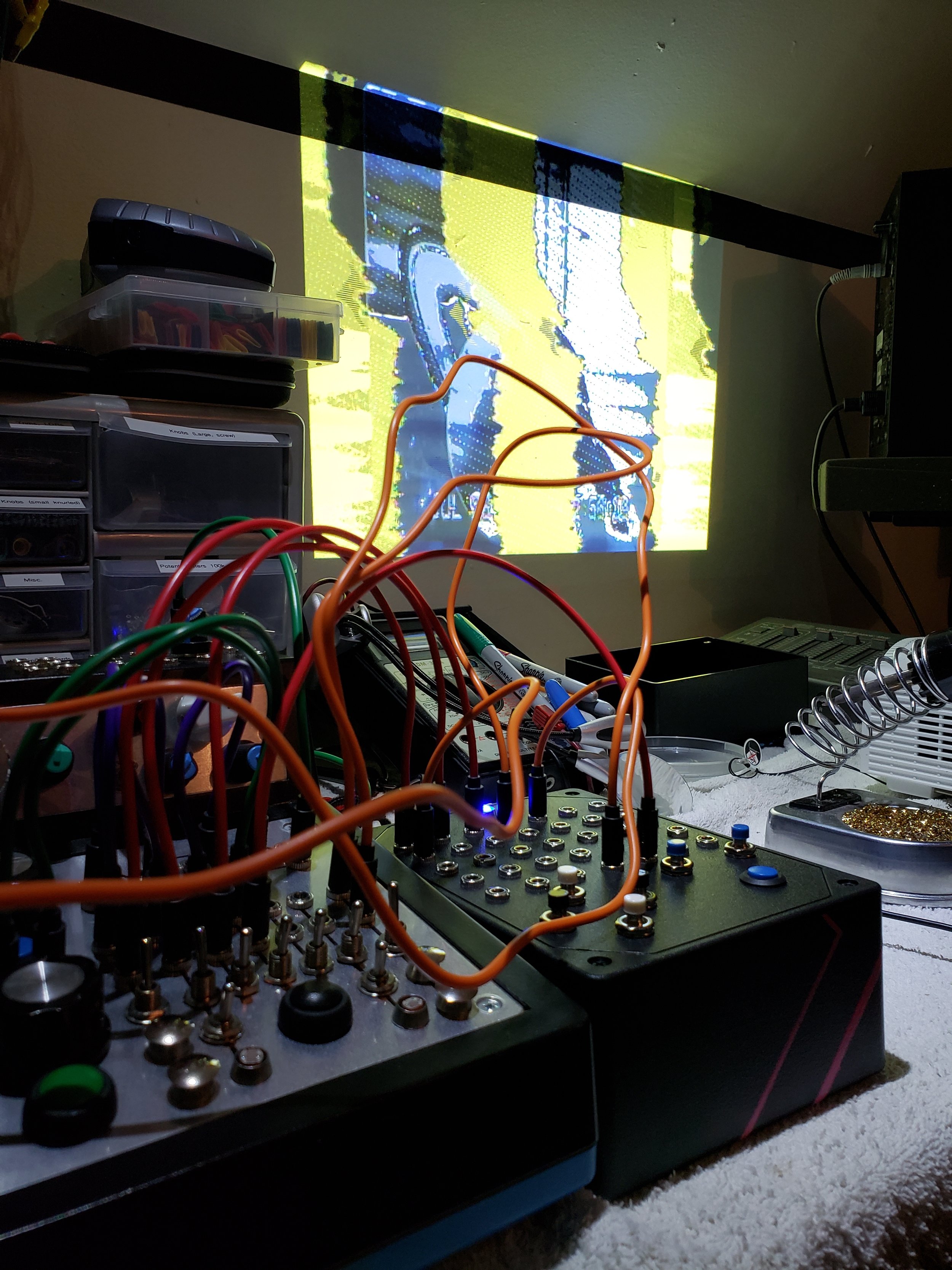
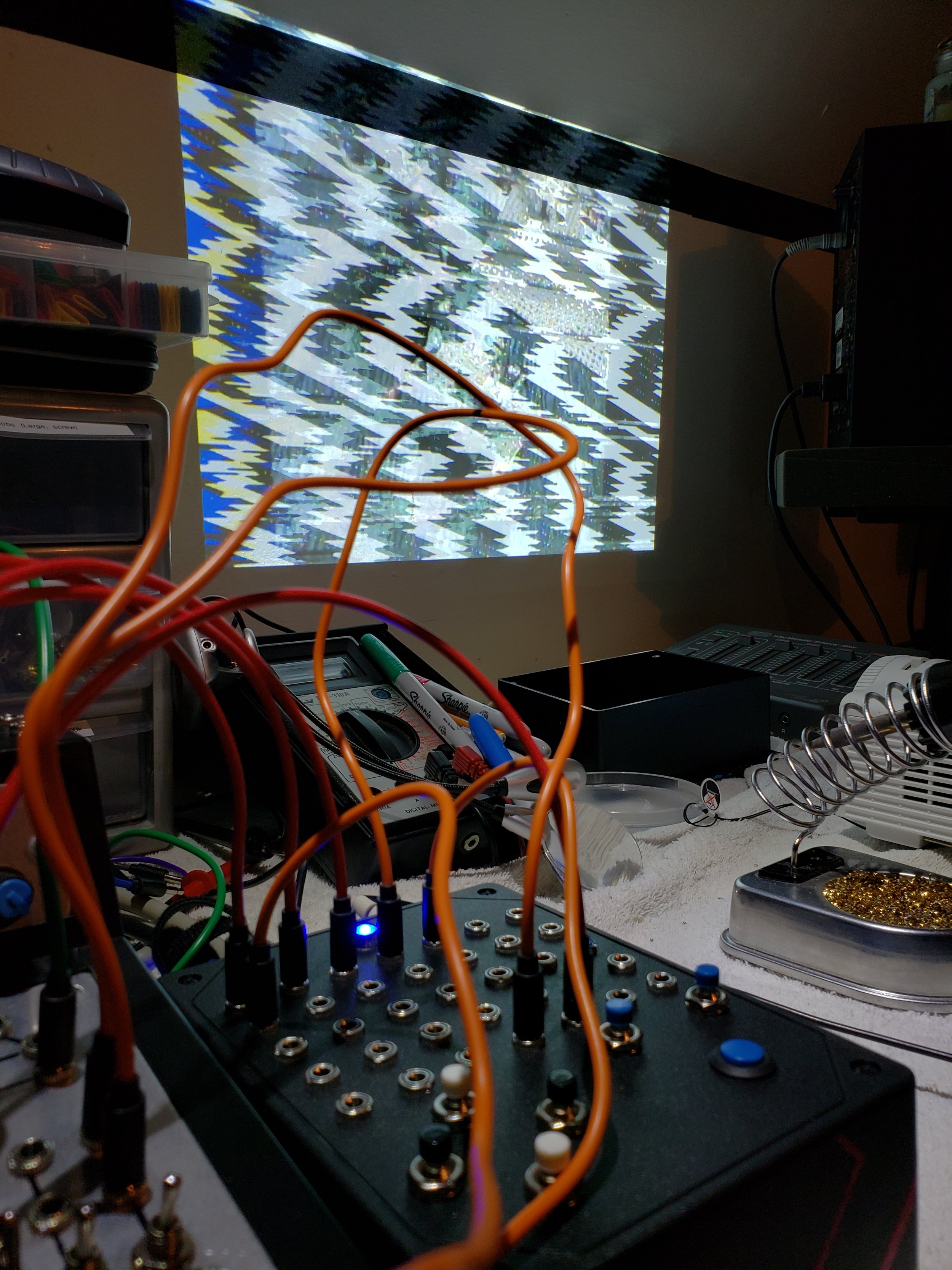


The top panel went through a redesign, and the initial build plan was a DB37 connection to run directly to the ModBox 37’s patchbay. Unfortunately there were a lot of video interference issues when using the DB37, so the patchbay was build directly into the box itself. I’m much happier with the end result actually, as it allows for a fair amount more flexibility when combining with other devices.
Reference & sourcing
These were very early notes while I was still learning - this was sort-of my first video device, so there’s some iffy info around here , especially the fact that I added breakout points for multiple ground pins of the VGA input. This isn’t an in depth guide, just jotted reference notes and points I found interesting.
The big Extron chip is where you’ll find lots of points of interest that are mostly-stable, and some points on the little 74HC combine nicely as well. I wouldn’t limit yourself to the points I labelled here - I just picked them due to space when I made this first build. You can find datasheets for both ICs online easily as well for some more detailed tinkering.
If you are looking to source one of these converters there are a few things to keep in mind - these aren’t as easy to come by in stores most of the time due to the prominence of the higher resolution converters. What you want to look for is a VGA to Composite converter that maxes out at 1024 x 768. The high res versions don’t have the RAM or buffer chips that let you do fun glitchy stuff! There are a ton of these that simply don’t have any branding whatsoever which you might find on eBay (usually in a dark blue case).
Some suggestions for grabbing those points off of the RAM chip: Use 30AWG stranded wire or smaller. Strip the end, twist the strands, and tin it enough so there’s a little extra solder on there. Use a fine point solder tip and let solder flow from your tinned wire onto the legs of the chip. If you overdo it you’ll end up shorting the pins and the solder can even flow under the IC which can be a massive pain.
Also - take note that this device can be 1/2 of a no-input feedback loop built with another converter! Check out The I.F.D. for an example of how this can be utilized to glitch out a feedback loop, and GVS008 which includes the ability to use this method to glitch both feedback & composite video sources.

