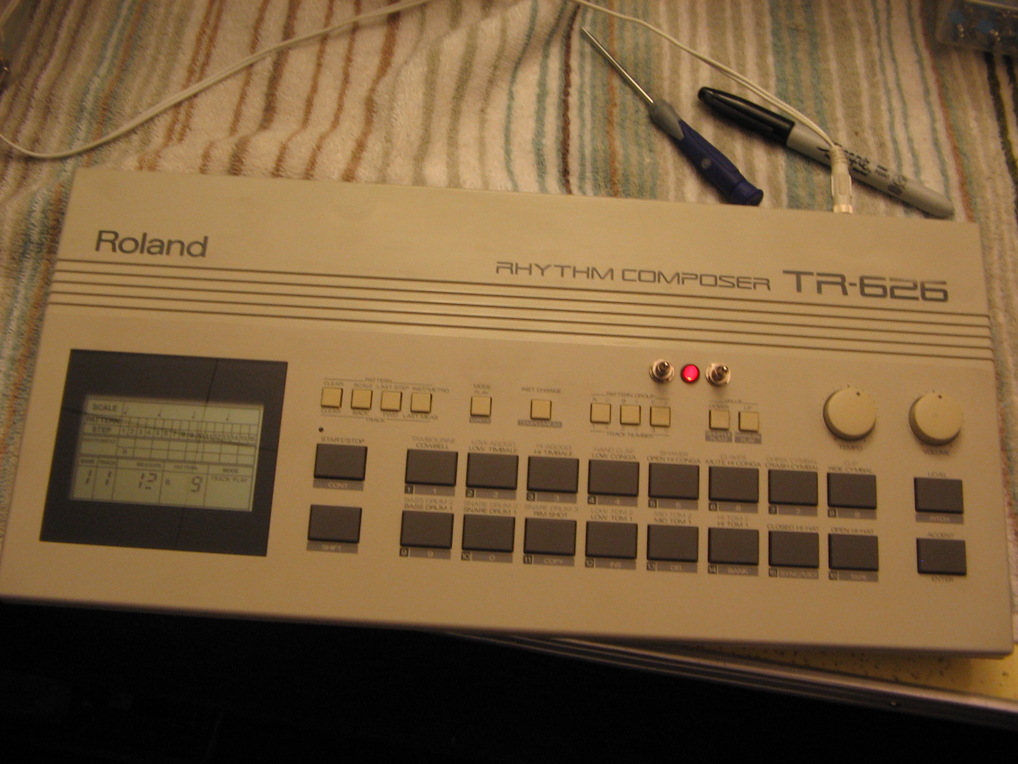
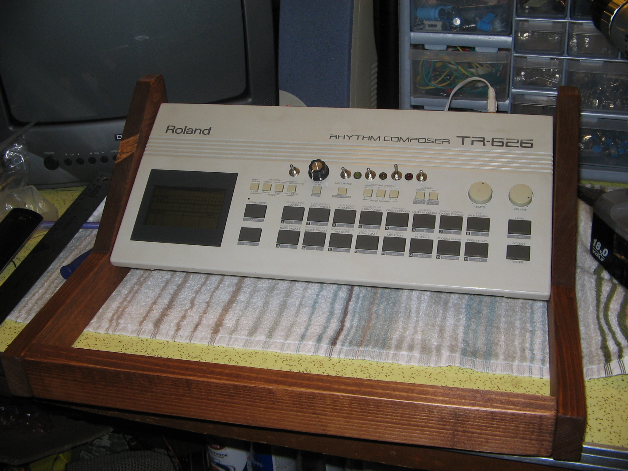
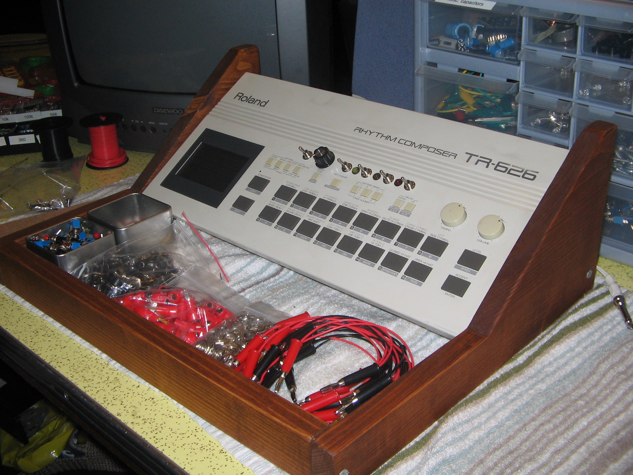
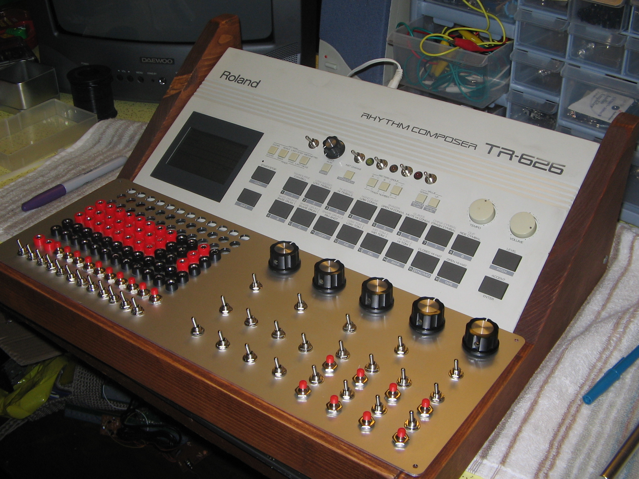
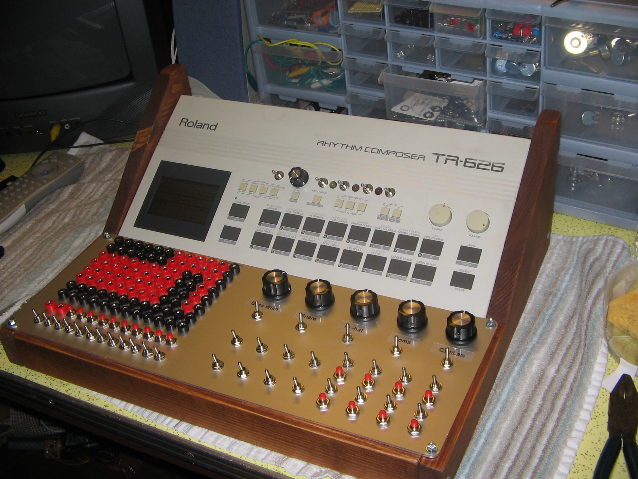
Circuit Bent Roland TR-626 Drum Machine
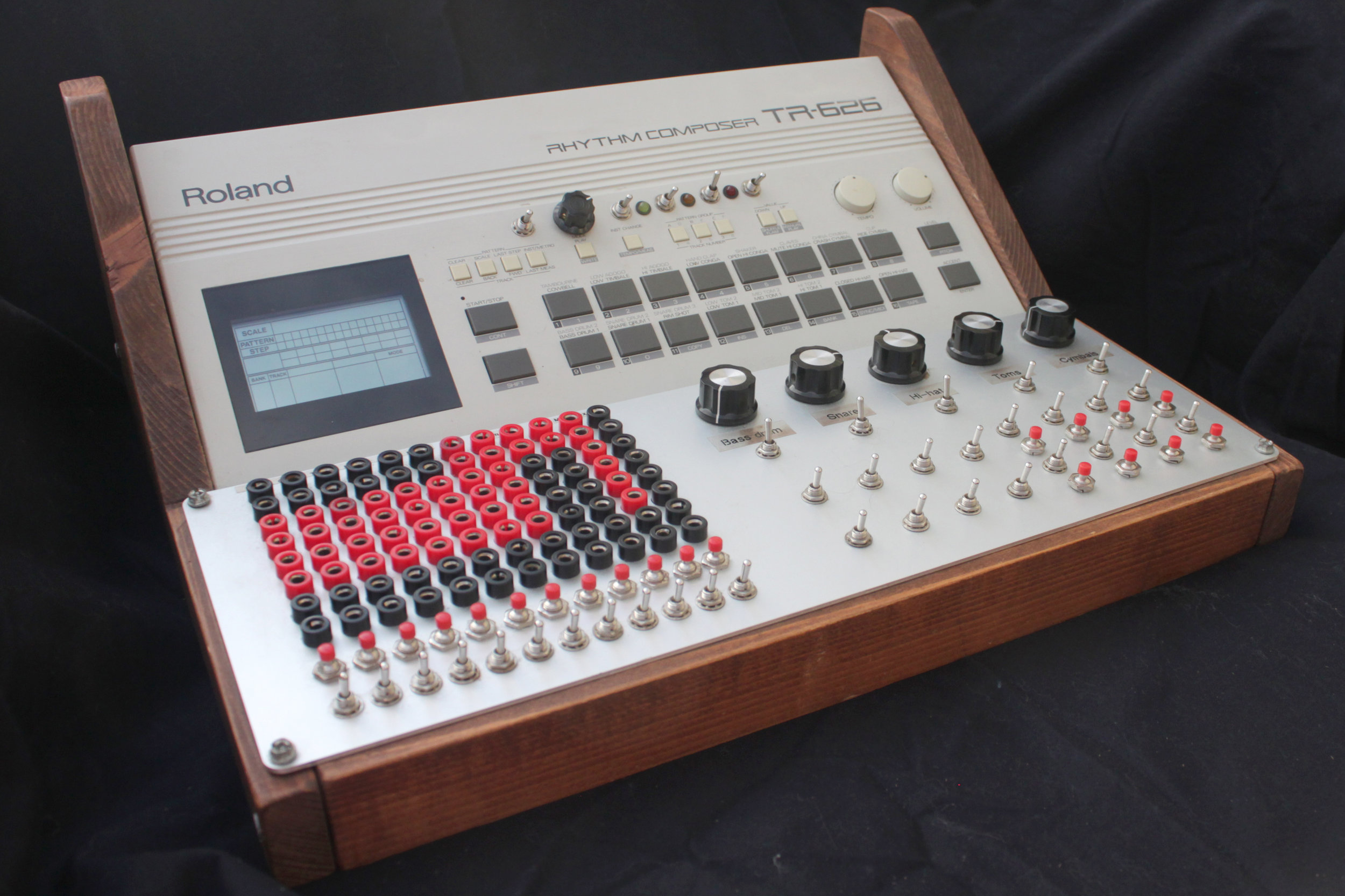
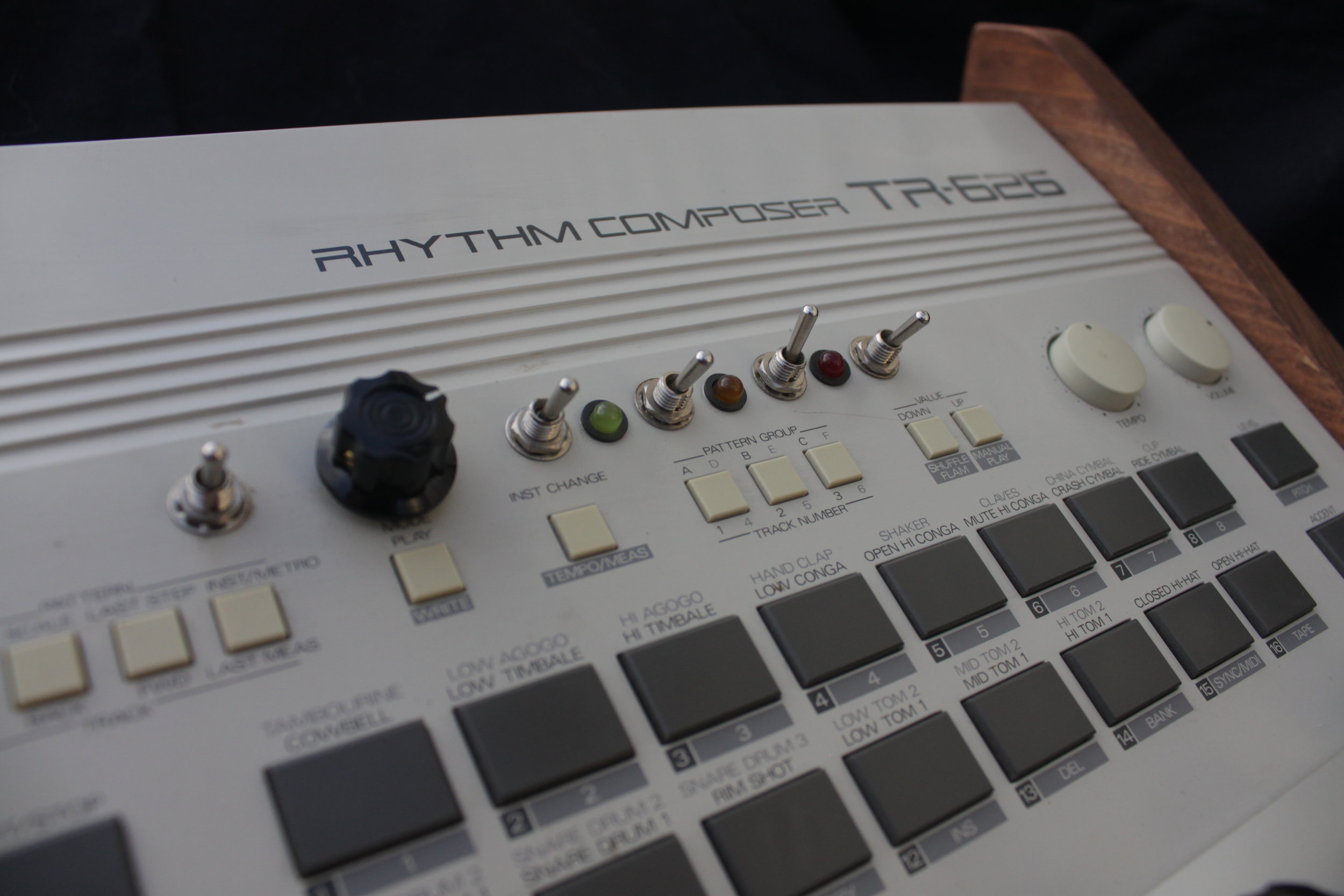
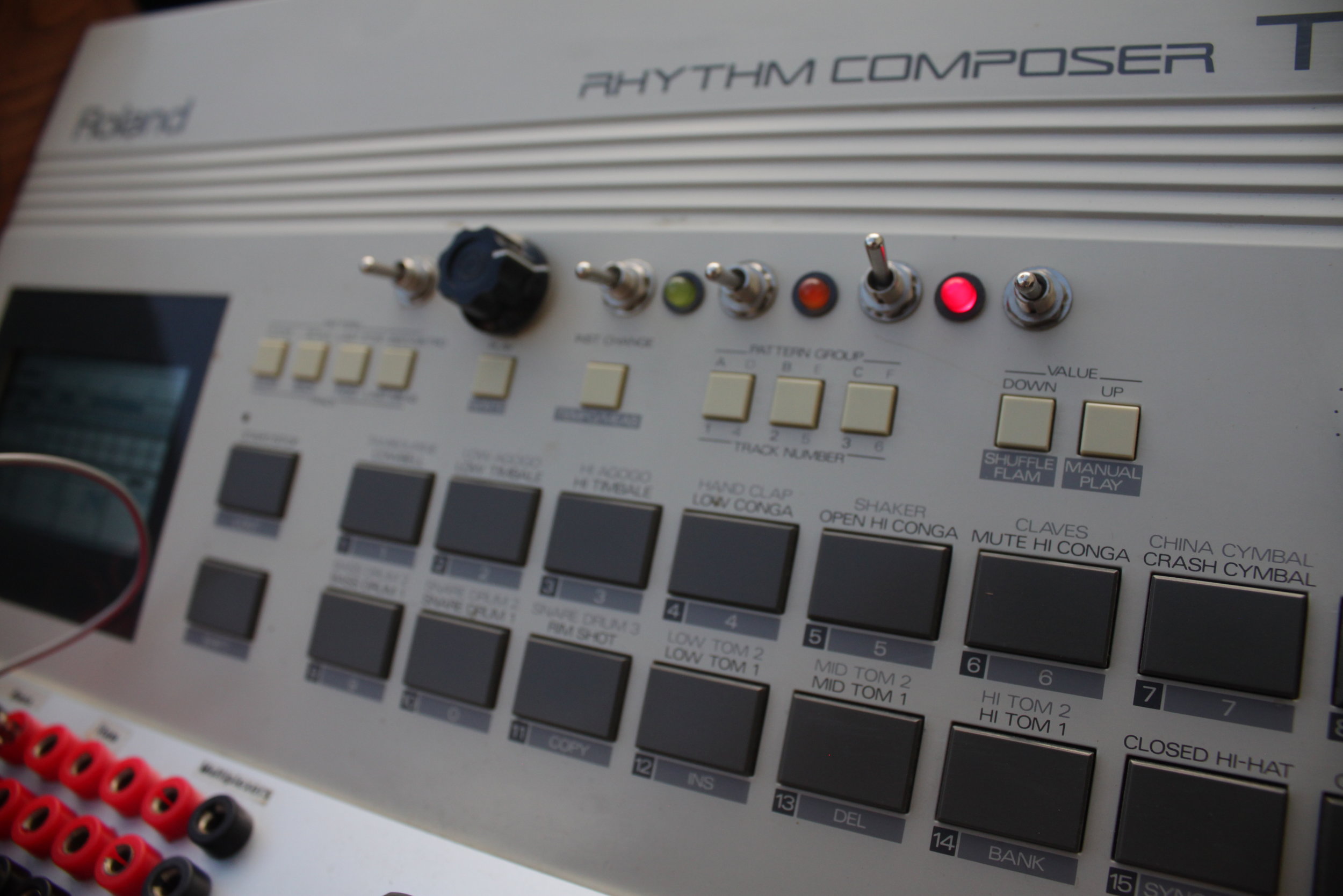
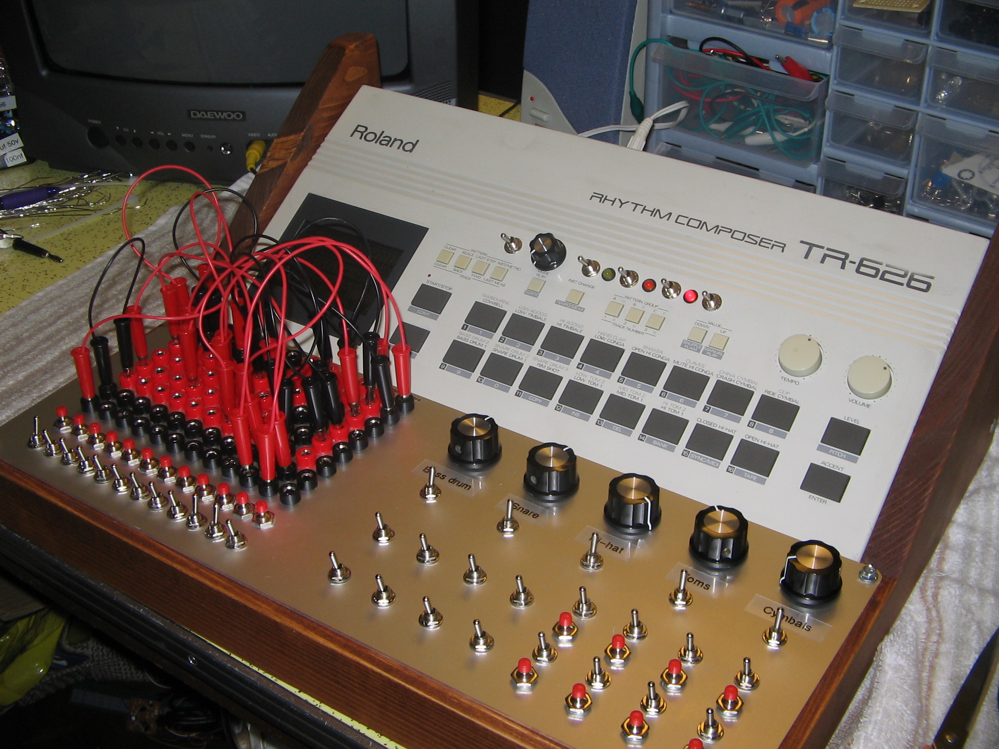
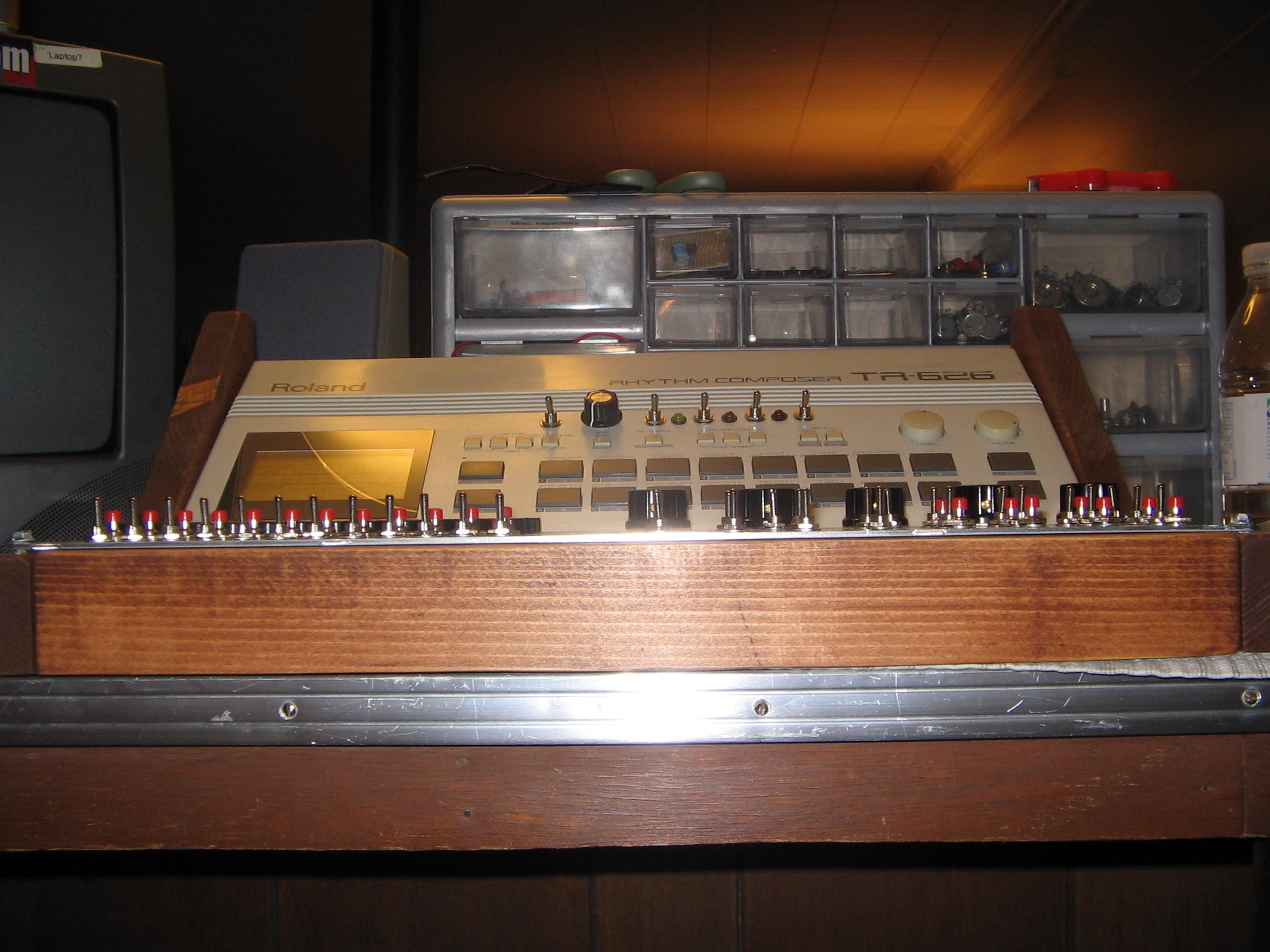
60x point patch bay, including dedicated sections for routing snare, crash, toms, hat, rims and kick sounds at standard or overdriven volume. Dedicated section for replacing individual drum sounds with squarewave tones; patch points for five octaves. 12 pairs of patch points with latching on/off switch and momentary pushbutton triggers for saving and controlling patches • 3x multiplexers (2x 3 point, 1x 6 point)
Volume control and mute switches for Kick, Snare, Hihat, Toms, Cymbals • 8x "Kit switch" triggers • 8x Ram scramble/fill triggers - momentary pushbutton trigger and latching on/off switch for each • Variable heavy distortion with on/off • Auto-filtered bassline accompaniment on/off • 2x misc. light distortion on/off • Pitch down on/off • 3x 1/4" audio output (all sounds replaced with squarewaves. 3 octaves.)
For those interested, a large collection of one-hit samples directly from this machine can be found in the Lagom Audio Sample Pack Volume 1 for free!
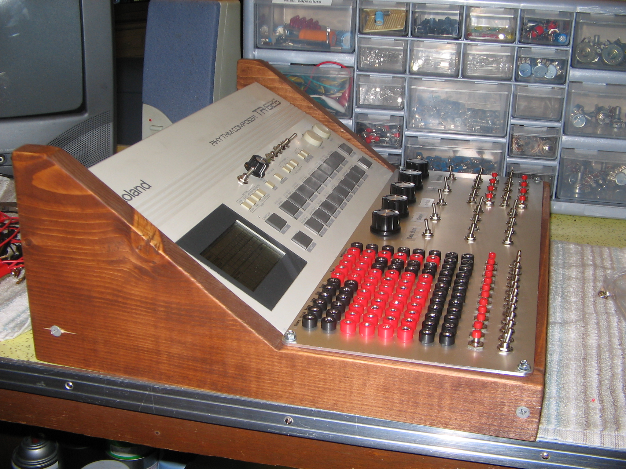
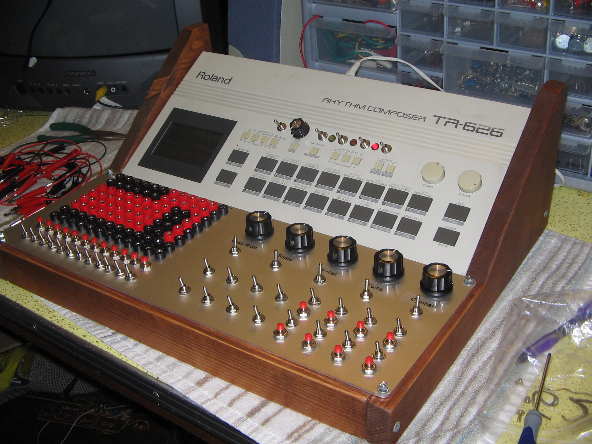
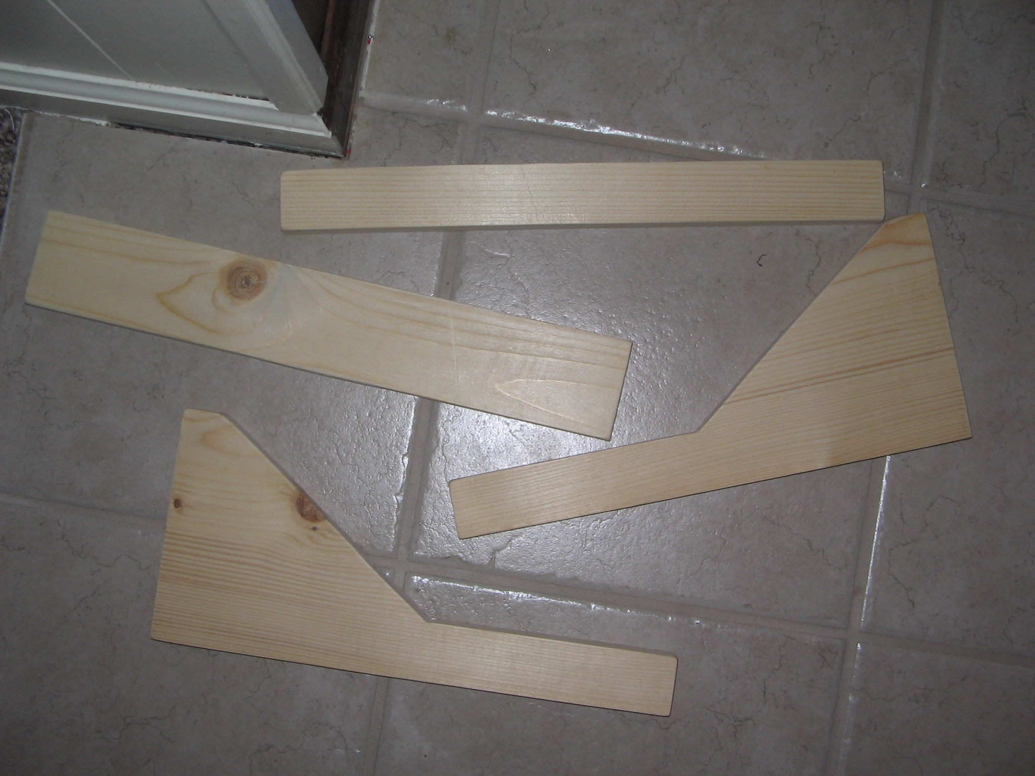
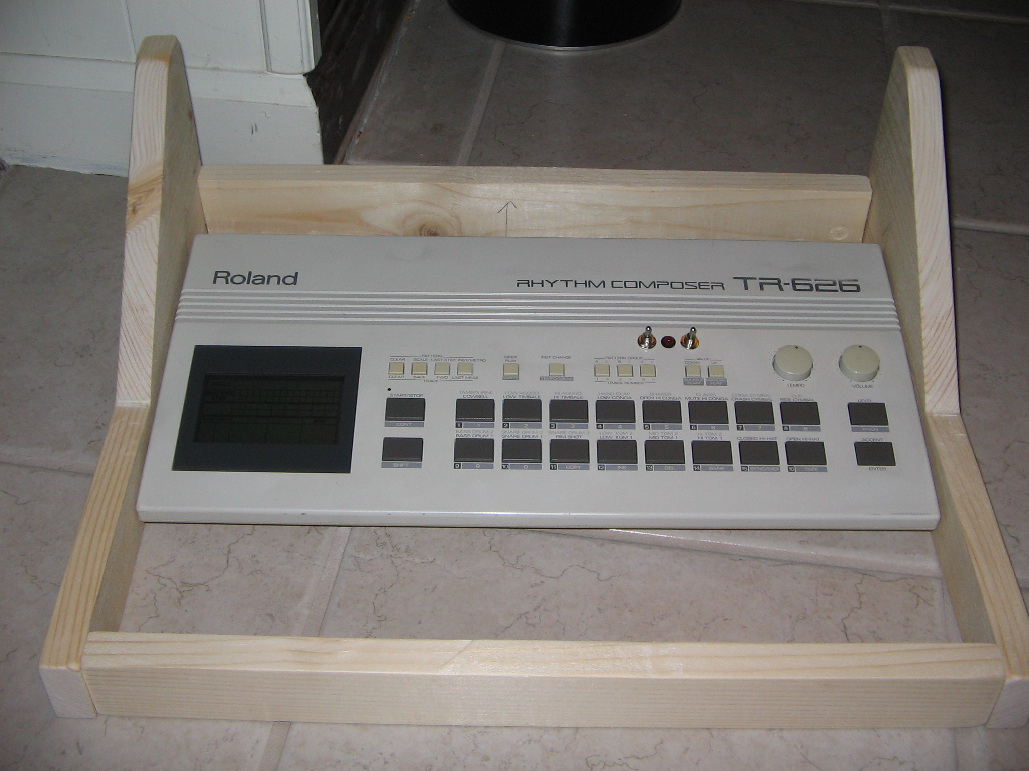
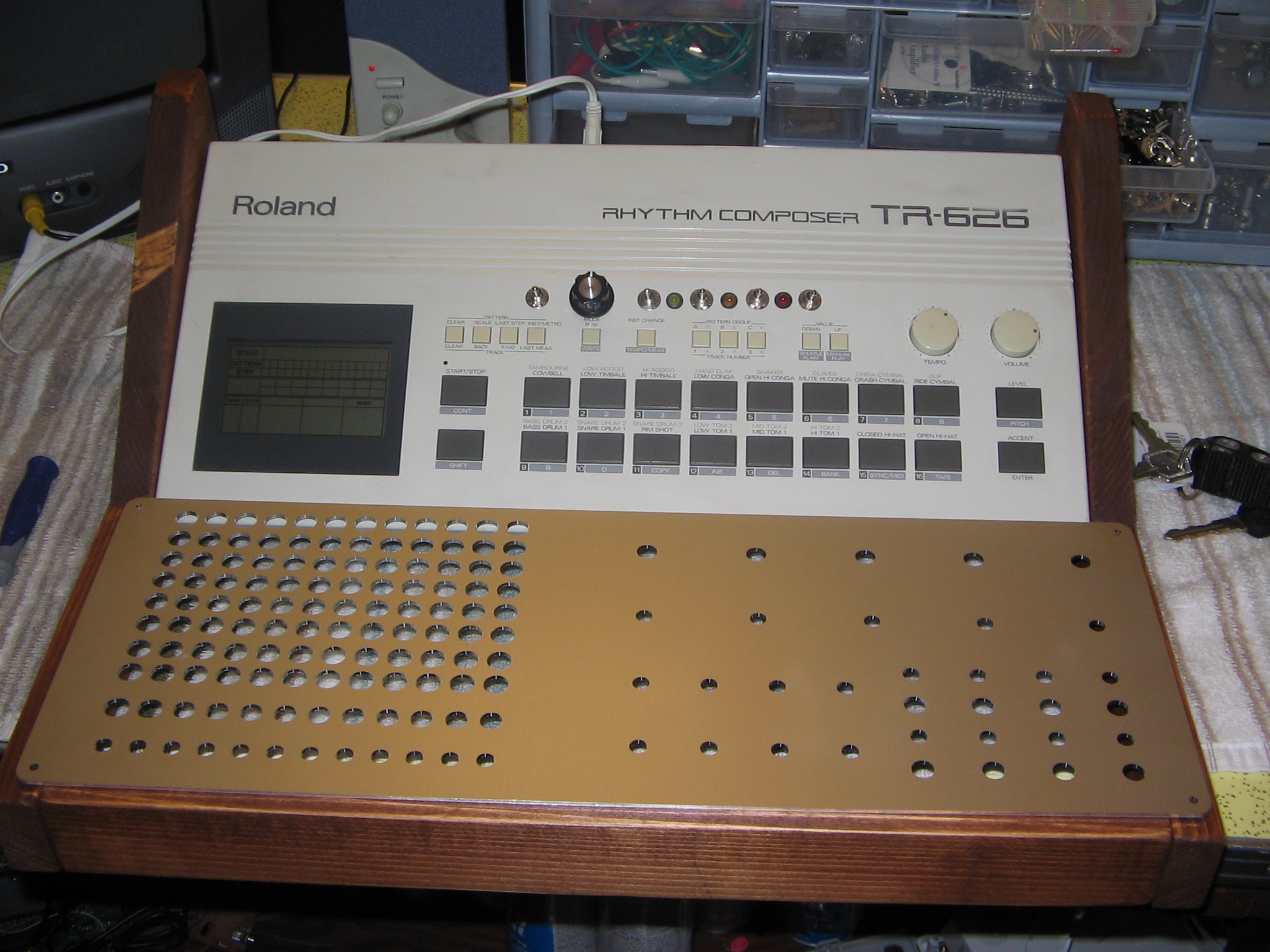
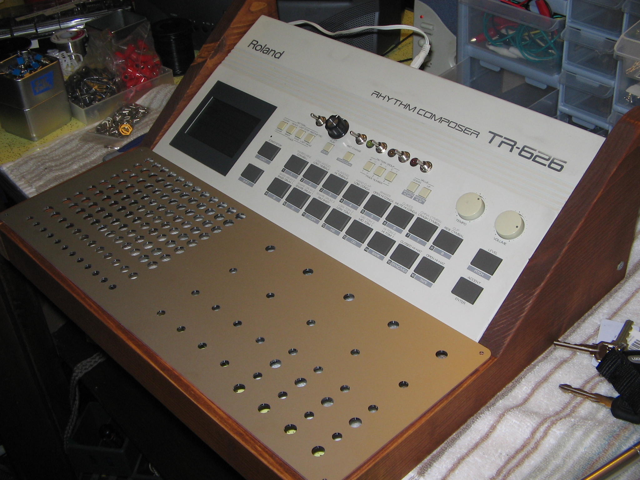
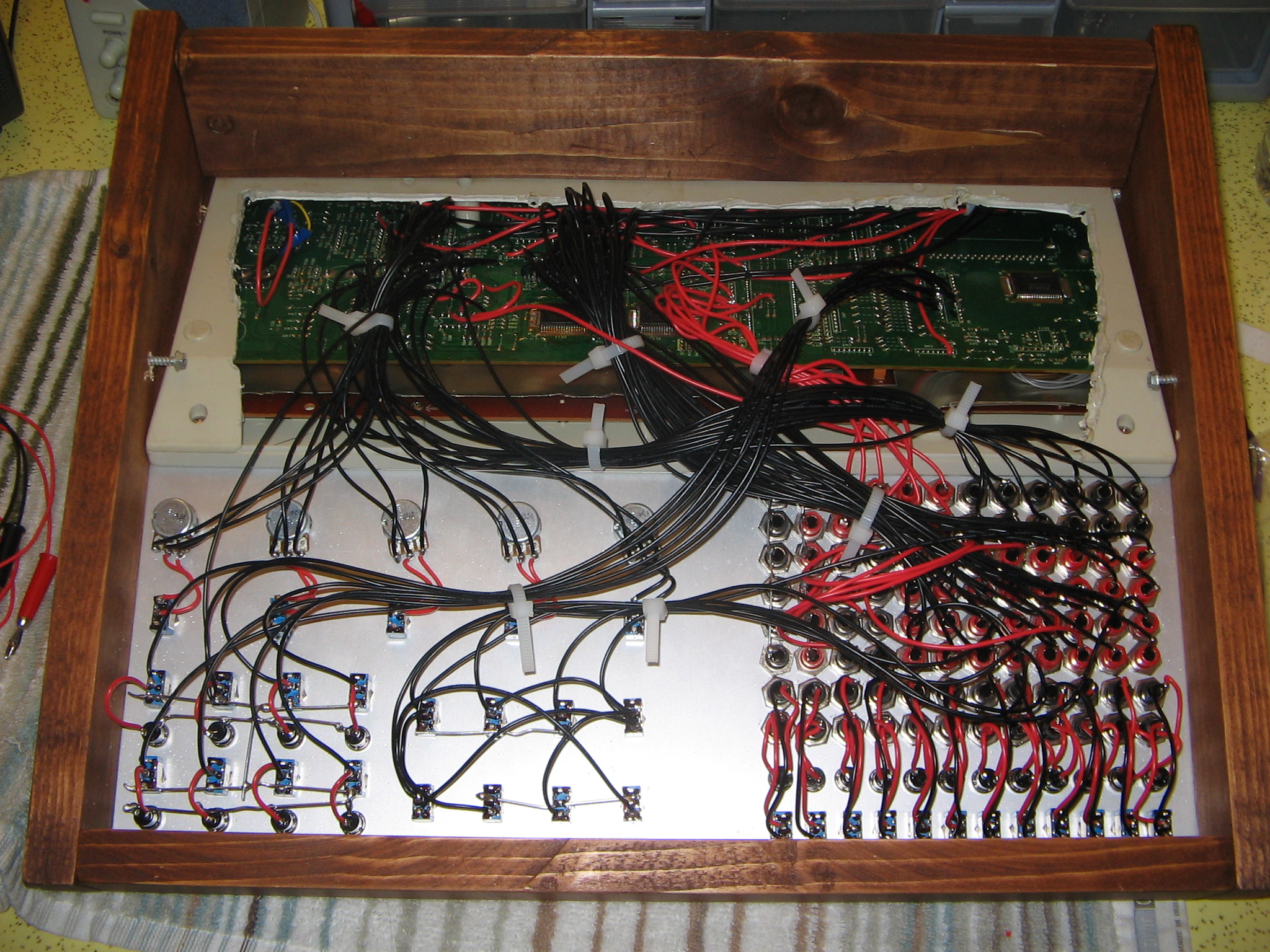
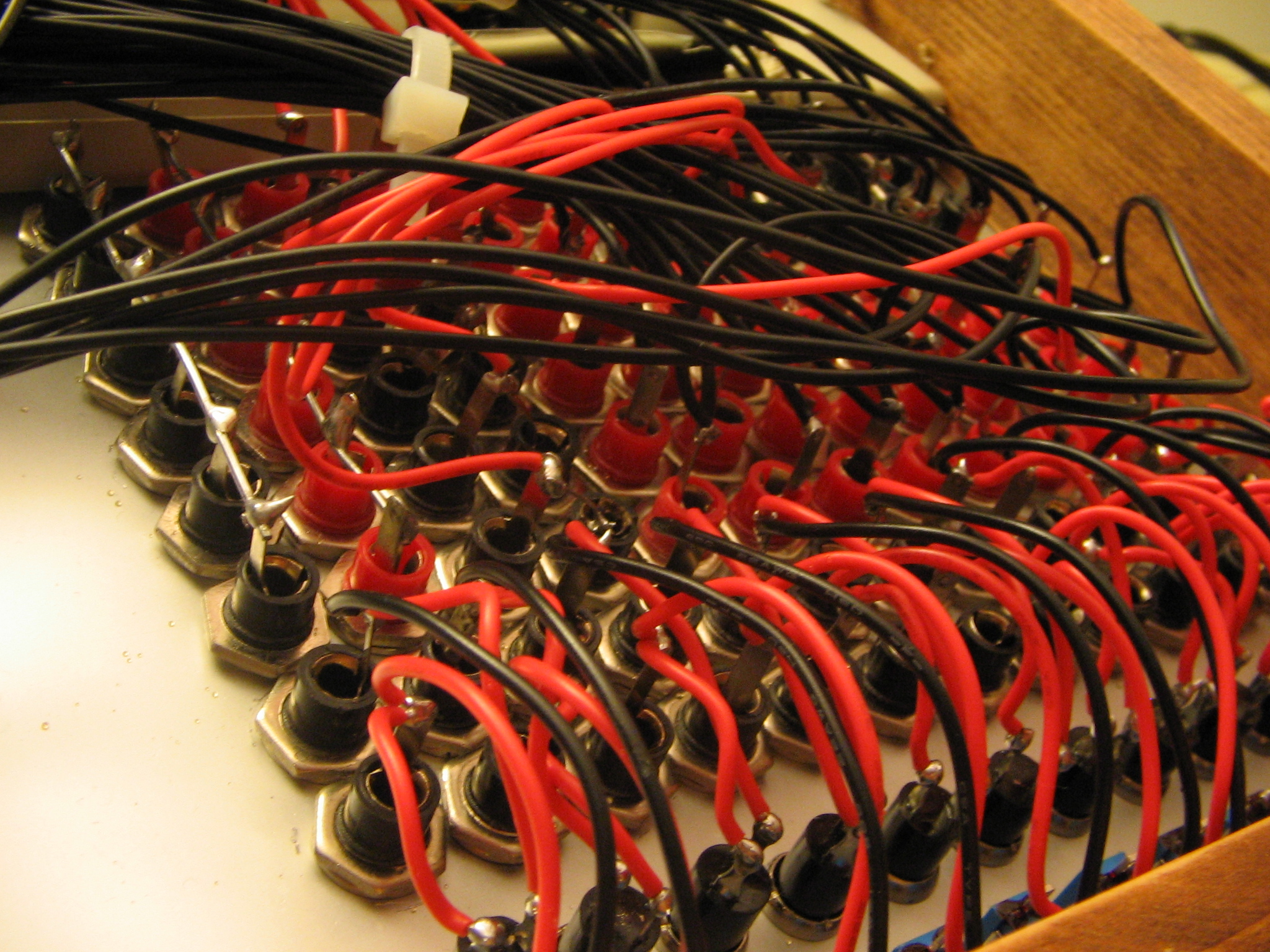
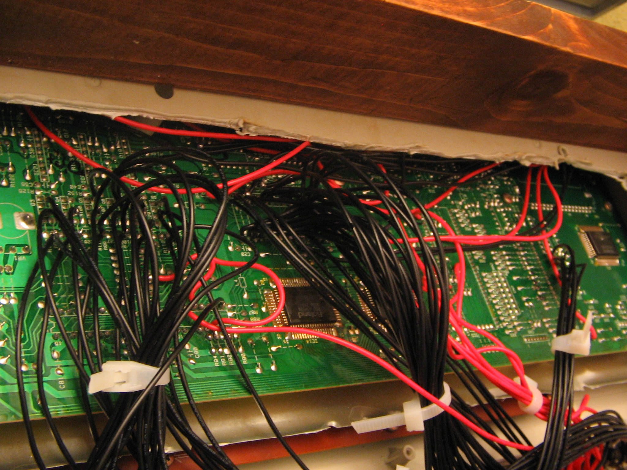
Progress photos
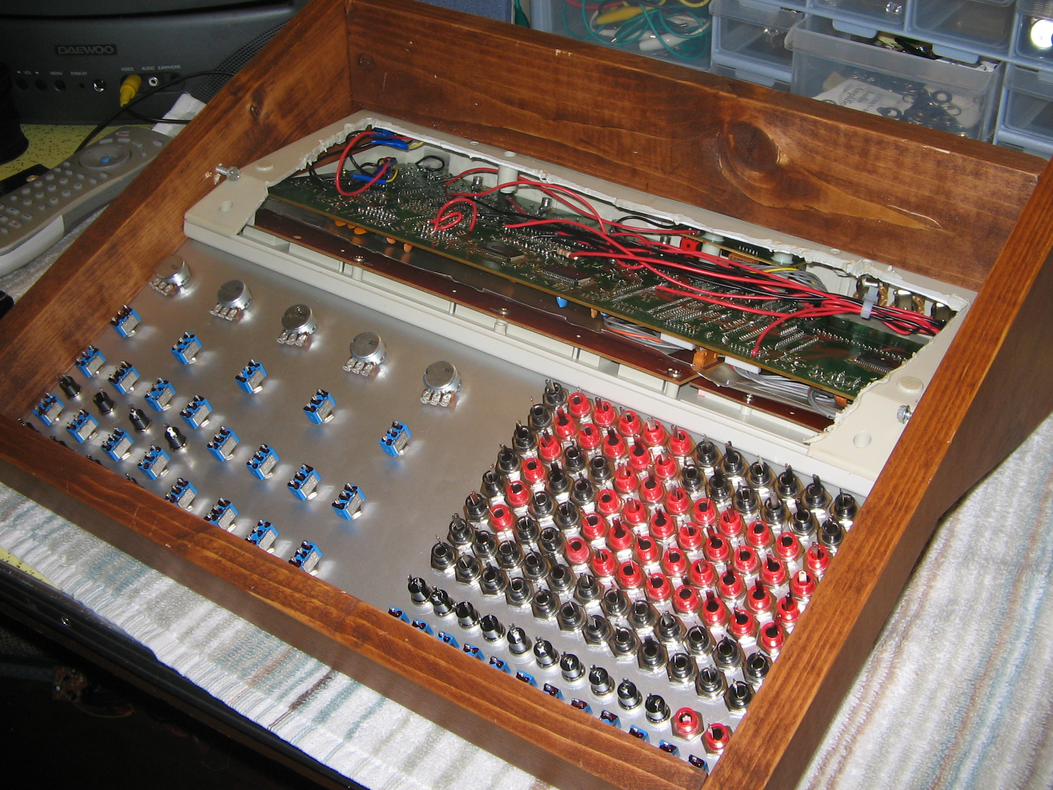
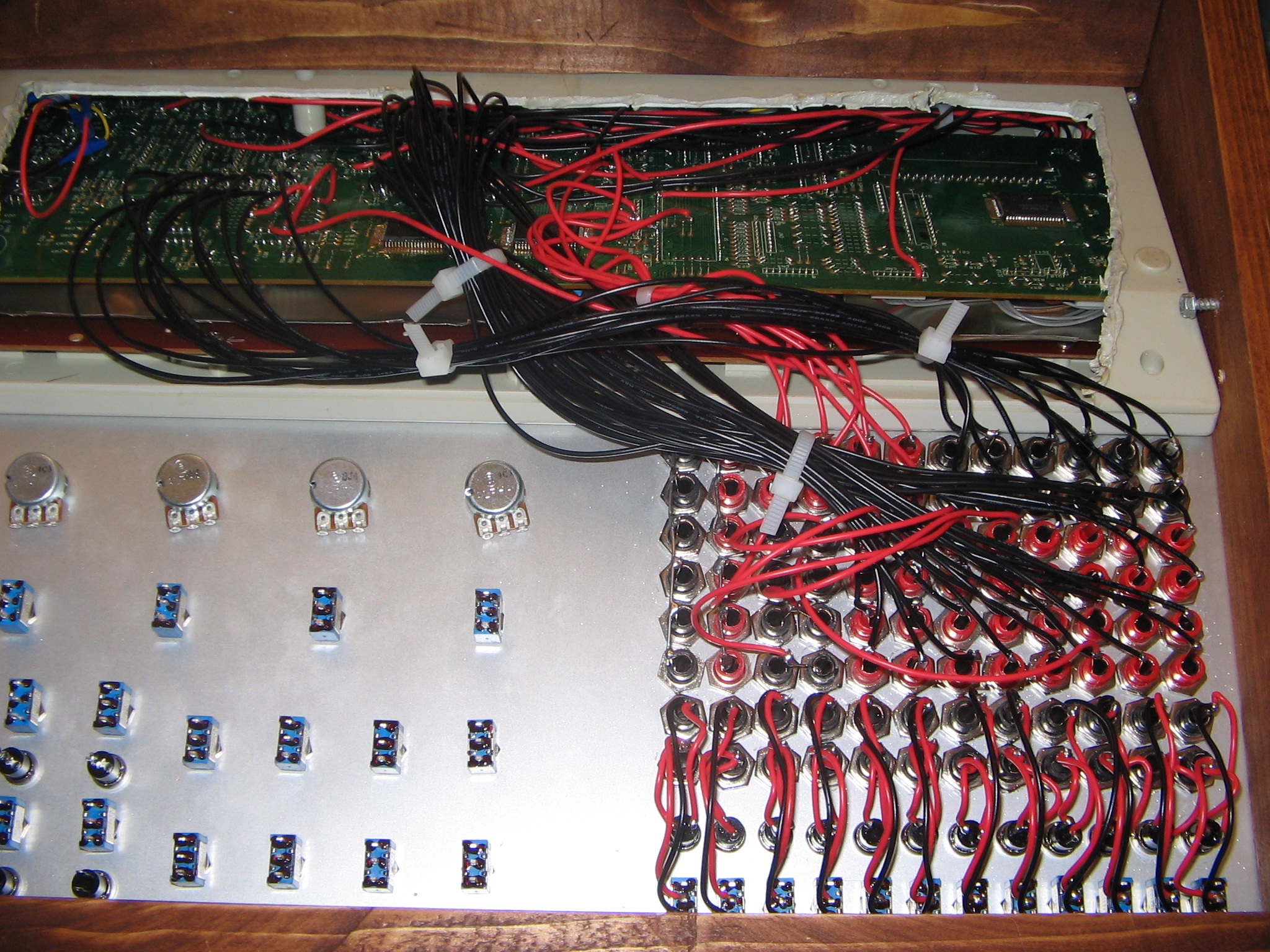
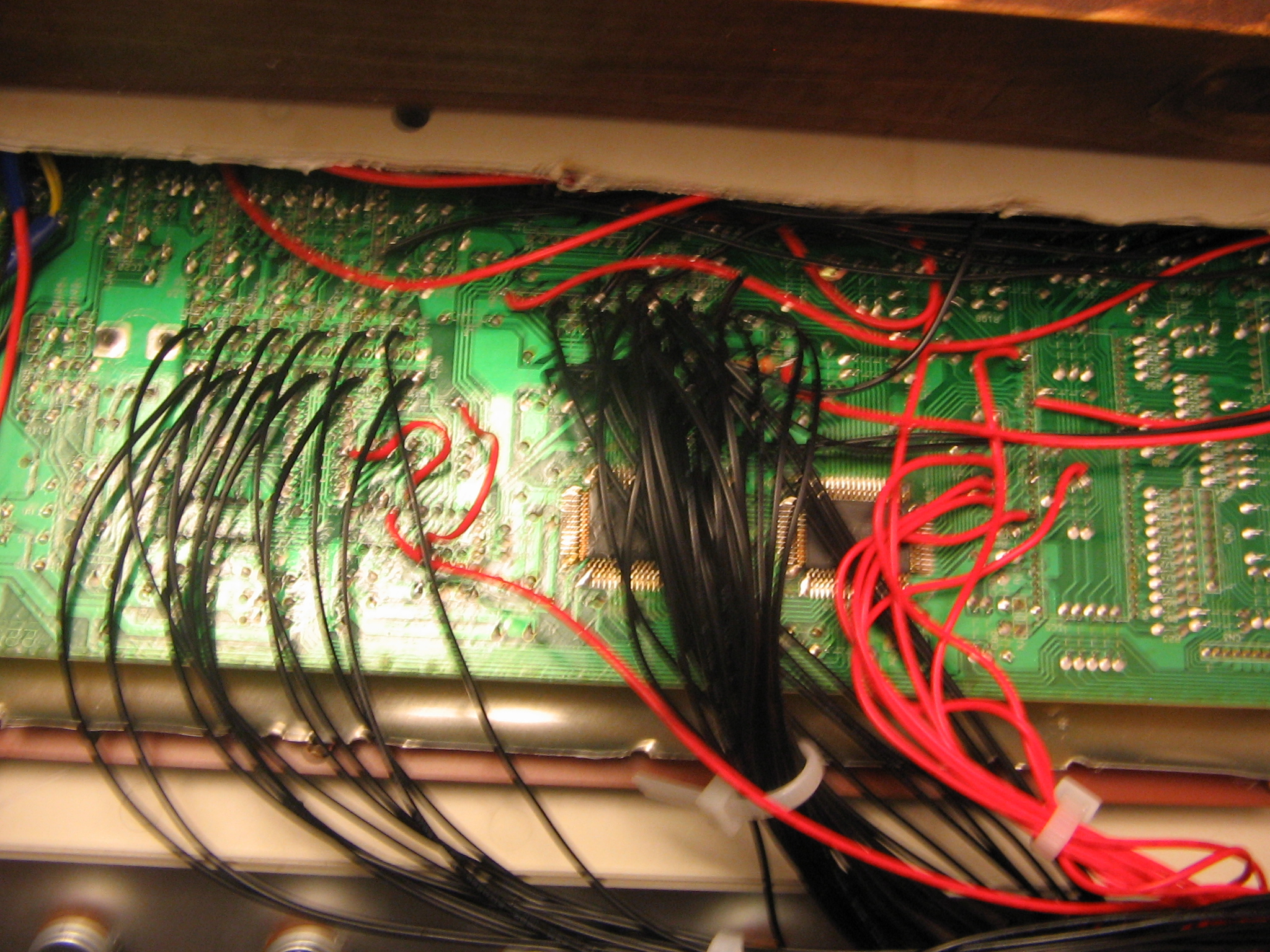
Build notes
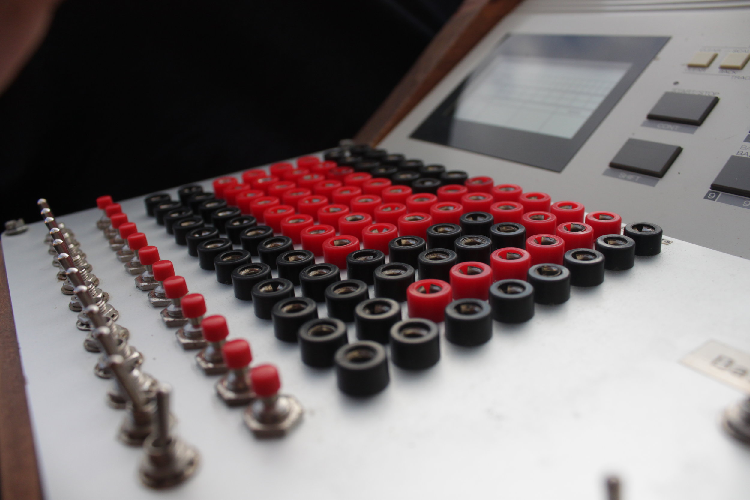
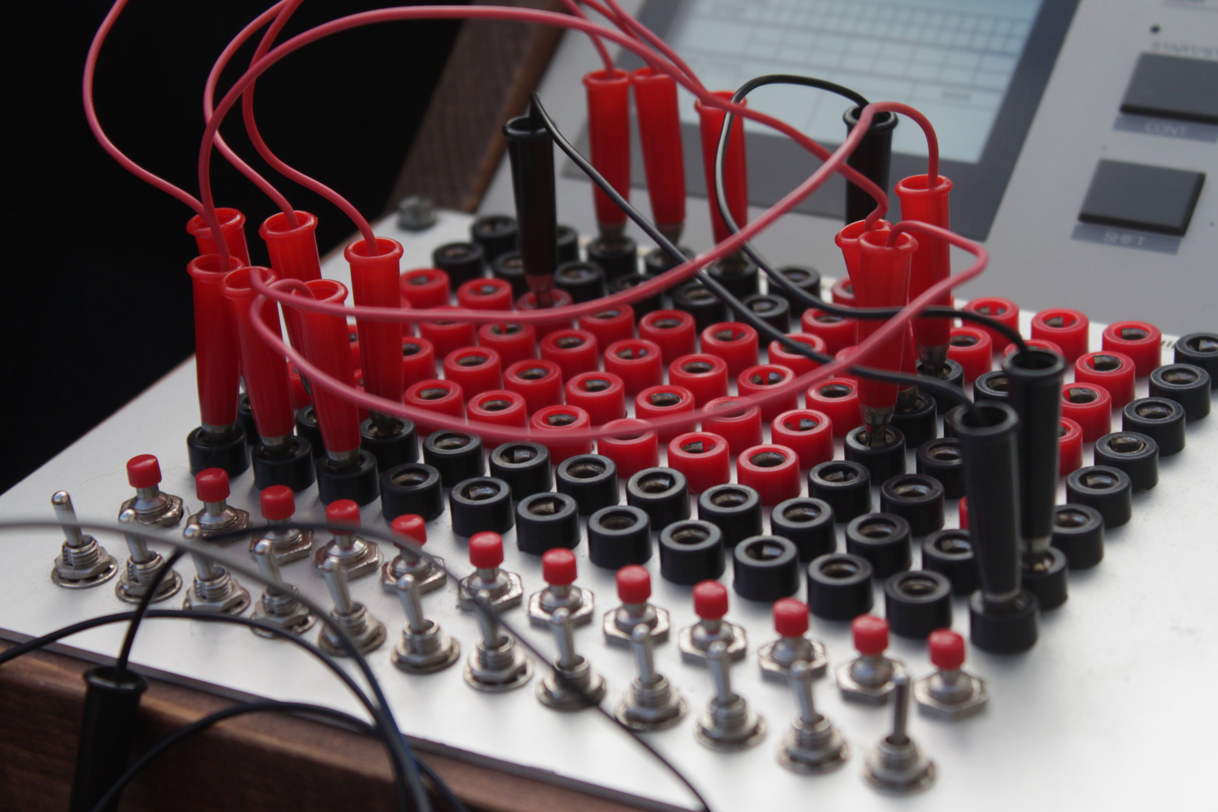
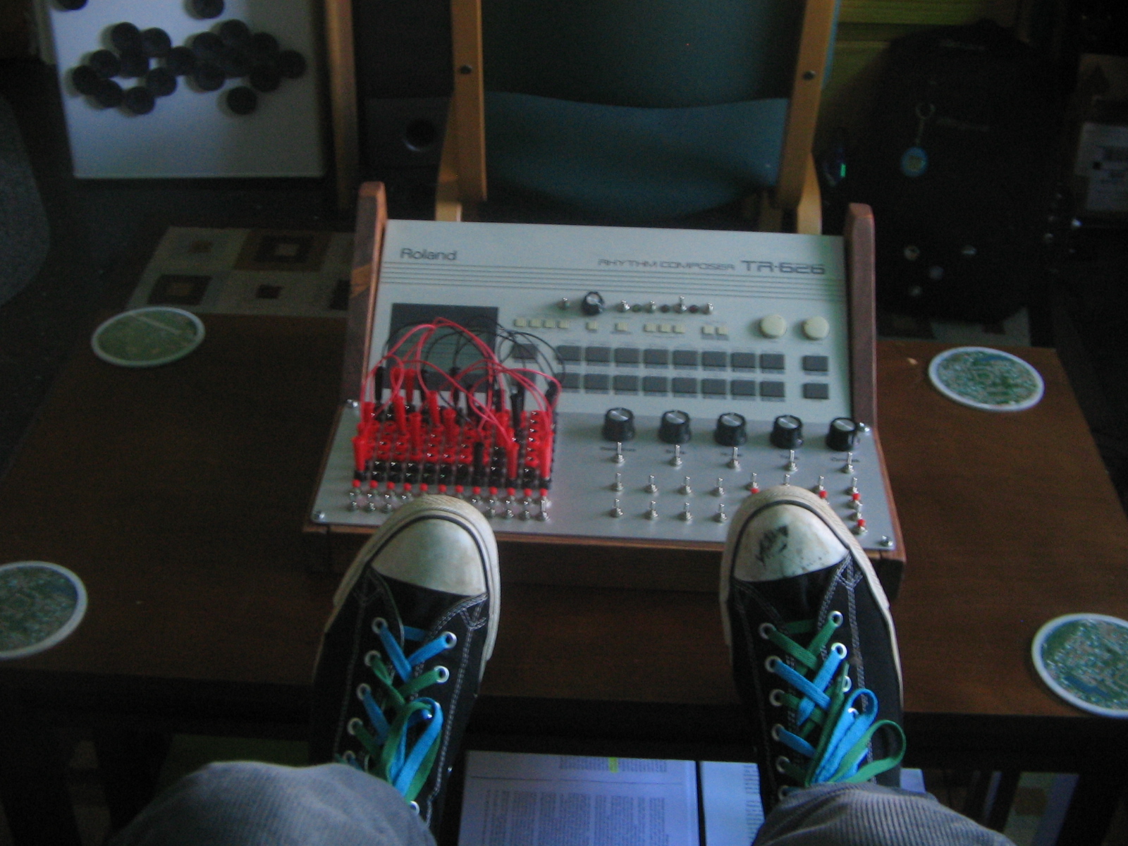
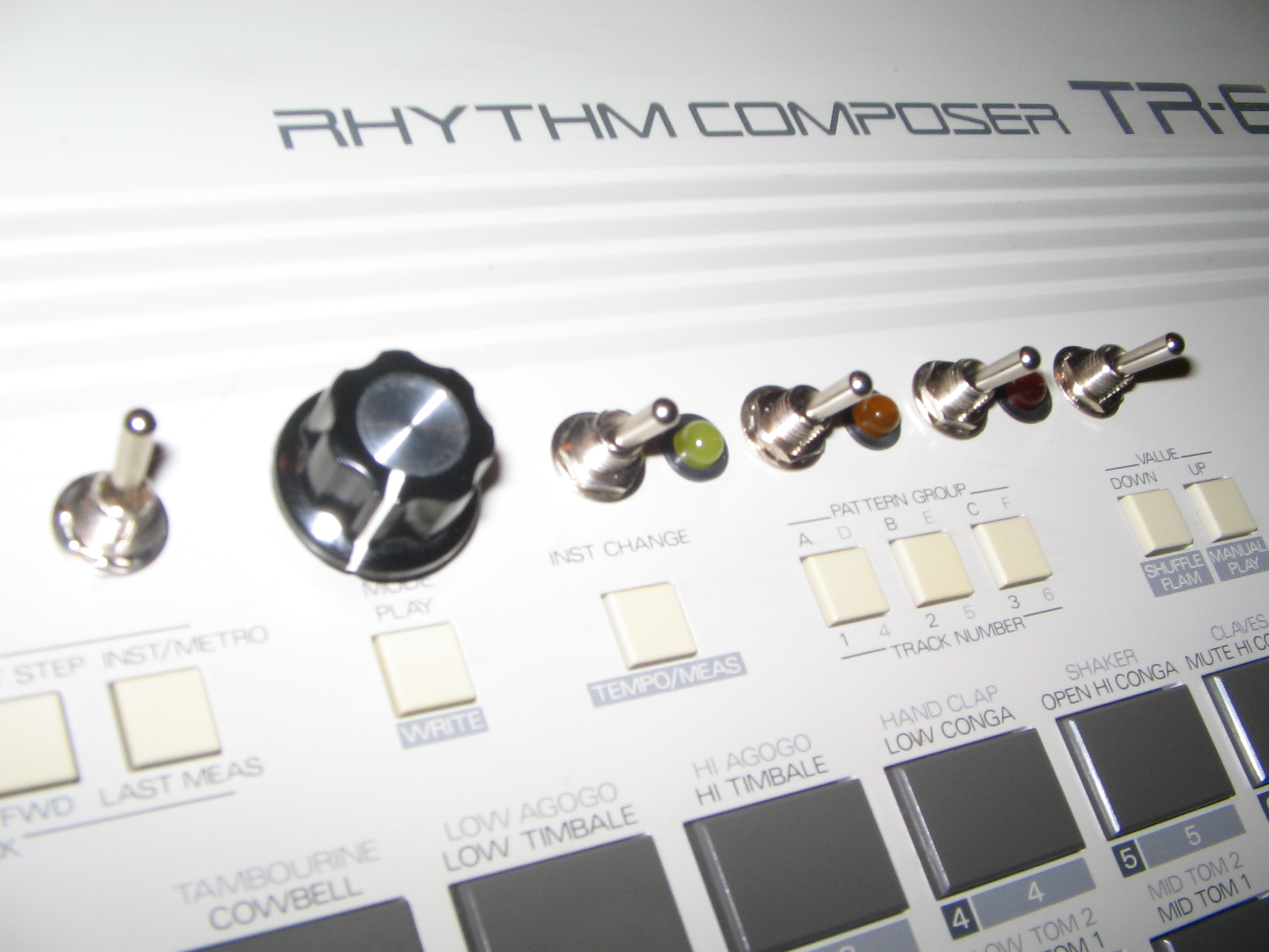
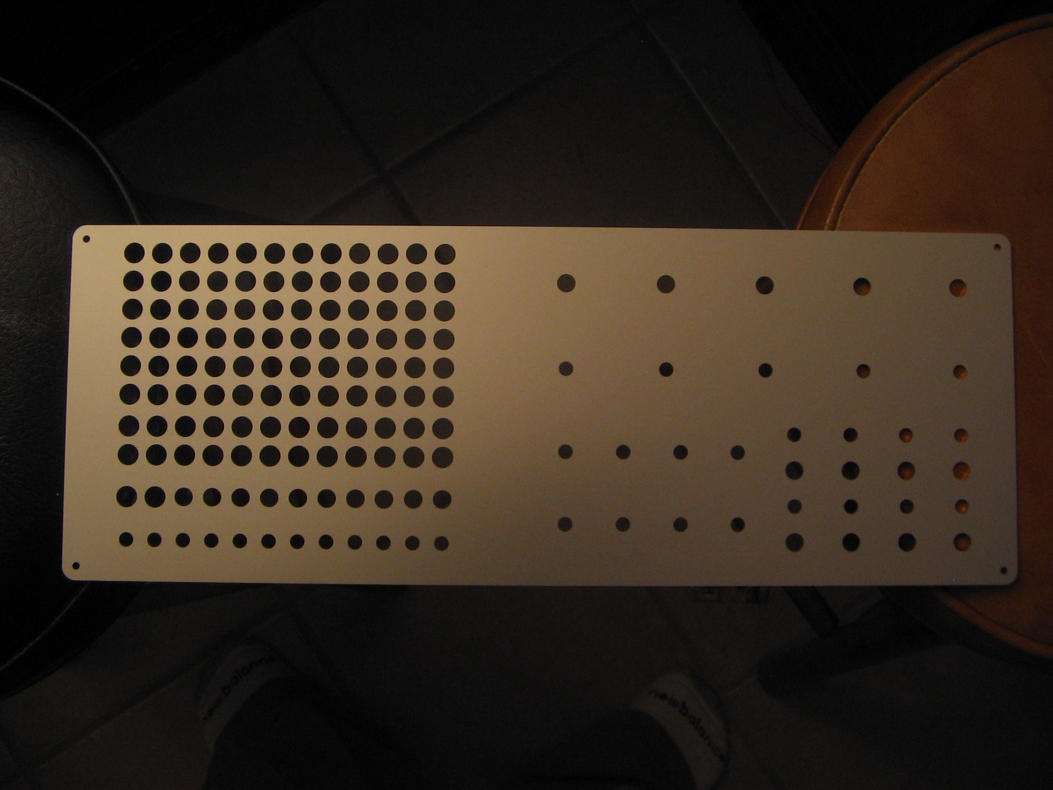
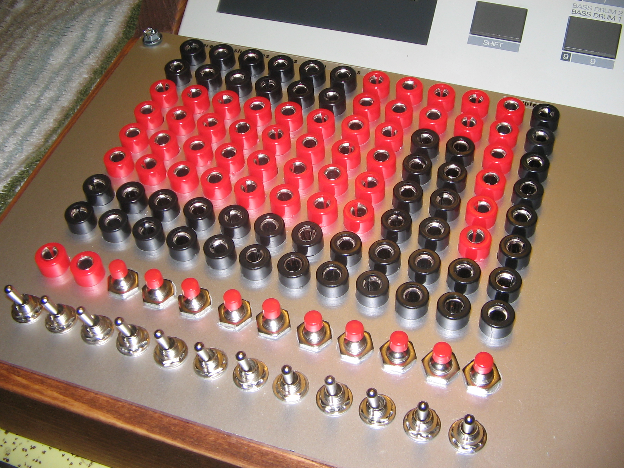
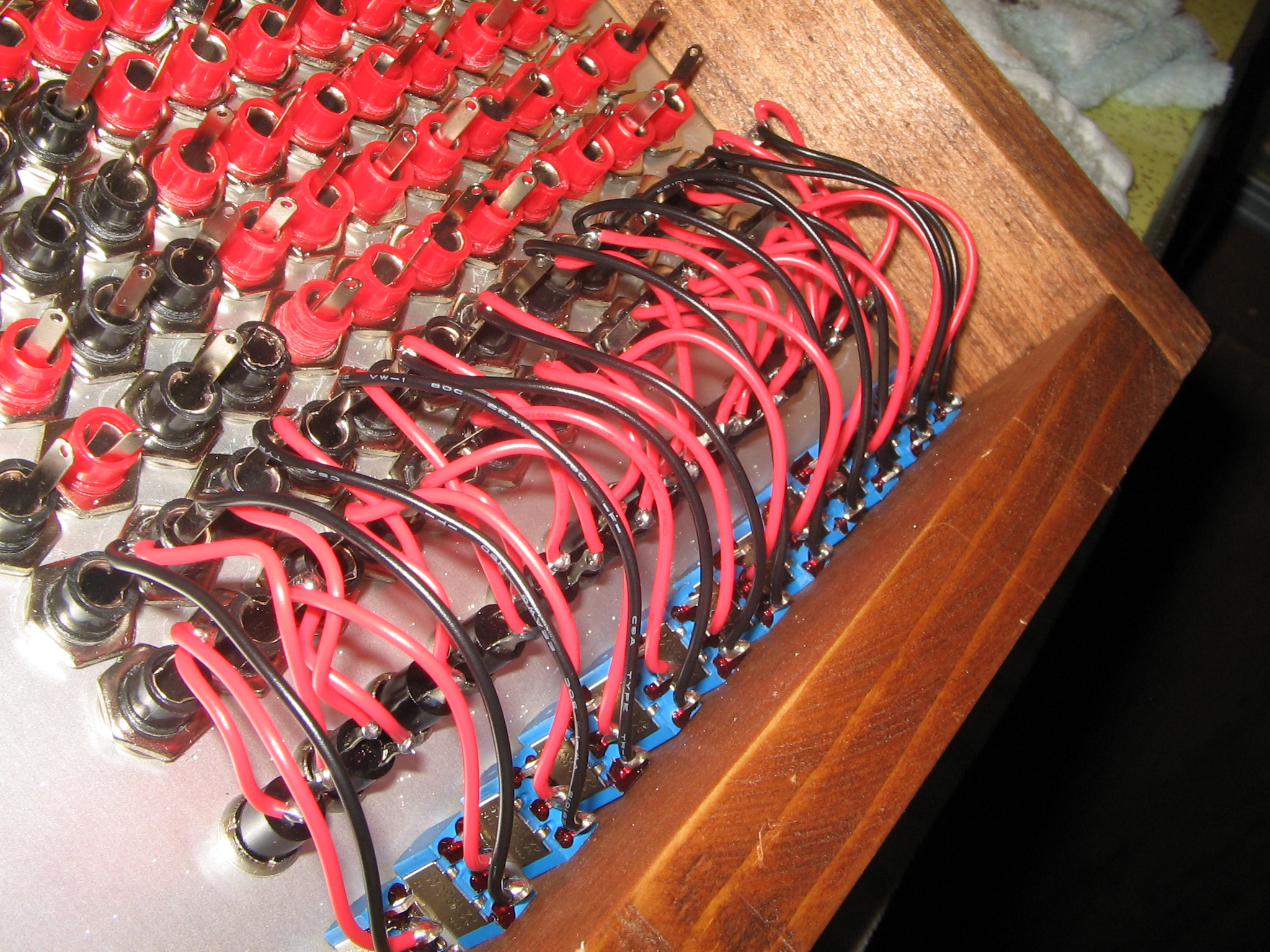
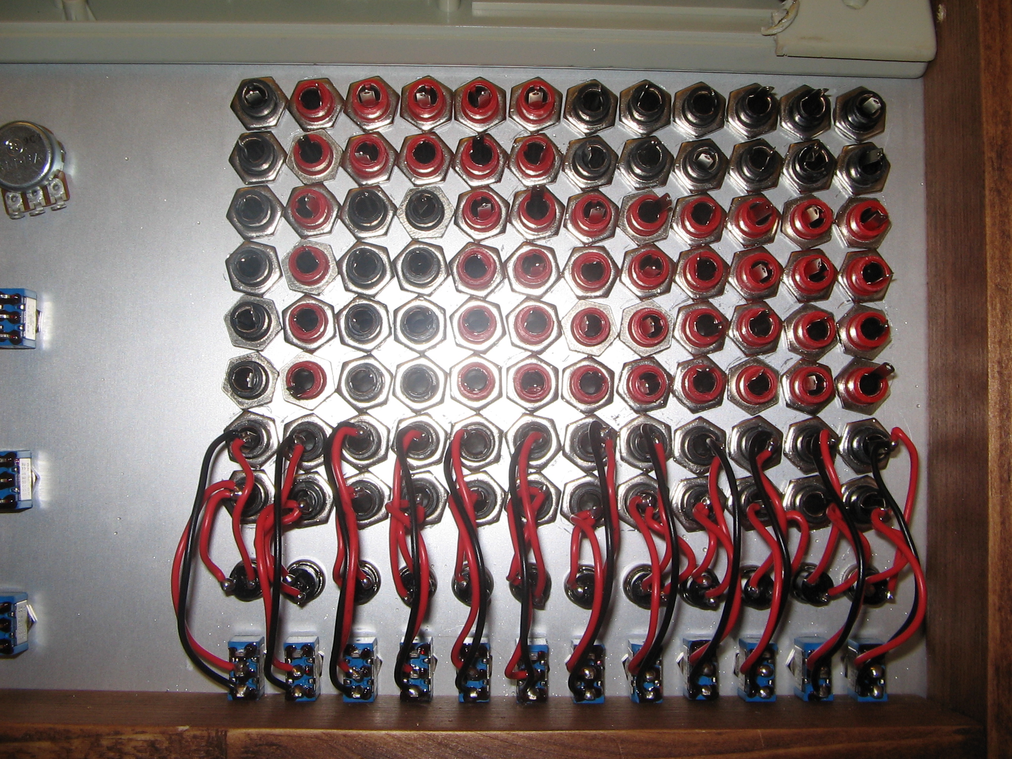
Let's start with the patch bay!

Orange = Resistor / Red = IC# / Black = IC pin / Blue = IC #15 pin# / Pink = Linked together / Green = Control Patches
Explanation and reasoning behind layout
IC15 is the big chip right in the center of the main board. It covers a bulk of this patchbay as it contains a ton of very interesting and usable bends. Burnkit2600 put together a wonderful map of every point-to-point combination on IC15 on their TR-626 page. The only combination to cause a crash would be 16 & 32, so keeping the entirety of this IC accessible seemed like a good idea.
The additional patch points on IC5 and IC18 also react well with IC15, so it was given it's own dedicated section.
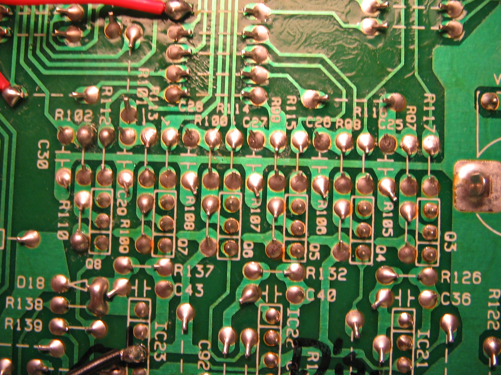
Resistor bank points
The resistor points, labelled in orange above, correspond to the bank of resistors coming from two of the 4051 multiplexer chips (IC18 and IC19) which output individual drumsounds. They are routed straight to the resistors and assigned as such:
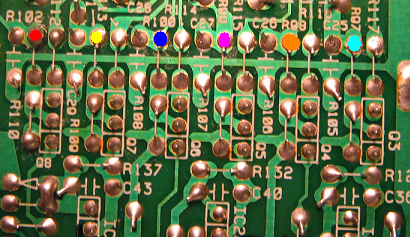
R102 (Red) - Snare
R113 (Yellow) - Crash/Ride Cymbals
R100 (Blue) - Toms
R99 (Pink) - Hats
R98 (Orange) - Rim
R87 (Light Blue) - Kick Drum
The points which I've colored above, when routed through points 27, 5, 6, 7, and 8 on IC15 replace the individual drum kit sound with a synthesized squarewave tone. These five different points each correspond to a different octave, and the default note for each squarewave is a G. This note can be altered through the programming of individual drum sounds within the TR-626. Running each of these outlines resistor points through points 11, 16, and 29 on IC5, as well as 3 on IC18, will cause various distortions to the individual drum kit sounds. Because I enjoyed the ability to replace individual drum kit sounds with squarewave tones I made an additional dedicated section for IC15 points 27, 5, 6, 7, and 8 so multiple drum sounds can easily be replaced with tones from each octave. These points are underlined in the above table.
For each individual kit sound I brought up to the patch bay, I linked both ends of the resistor (labelled with A and B in the above table). This is simply because on one end of the resistor the volume will be at its standard, while on the other end it's still very loud and harsh. Having both sides available for routing allows a bit more flexibility.
The individual drum sounds coming from IC18 and IC19 are not limited to the ones I've listed above, so it would be sensible to check other areas of the ICs for additional kit sounds you might wish to control. You might try running these additional sounds through the myriad of other points on the board as well, but always keep in mind that damage and crashes can occur if shorting anything to the main power circuit, and that the RAM chip (IC2) is incredibly unstable.
Patch bay control
The simplest thing to do, and perhaps the most useful part of the patch bay. It can be difficult to remember what patch combinations yield certain results, and it's also very impractical to attempt and patch everything live if there are certain alterations to the sound that you end up wanting to come back to. For example, I get a ton of use out of IC#18p3 to IC#5p3, a patch that gives everything a sort of soft, crunchy sound. I almost always have those two points linked to C12a and C12b on the control bay so if I want that sound I've got access to it without any patching needing to be done. Having not only an on/off switch but a momentary on/off button allows for some flexibility in live use as well. Especially useful for sprinkling in minor flourishes here and there instead of letting them run amok.

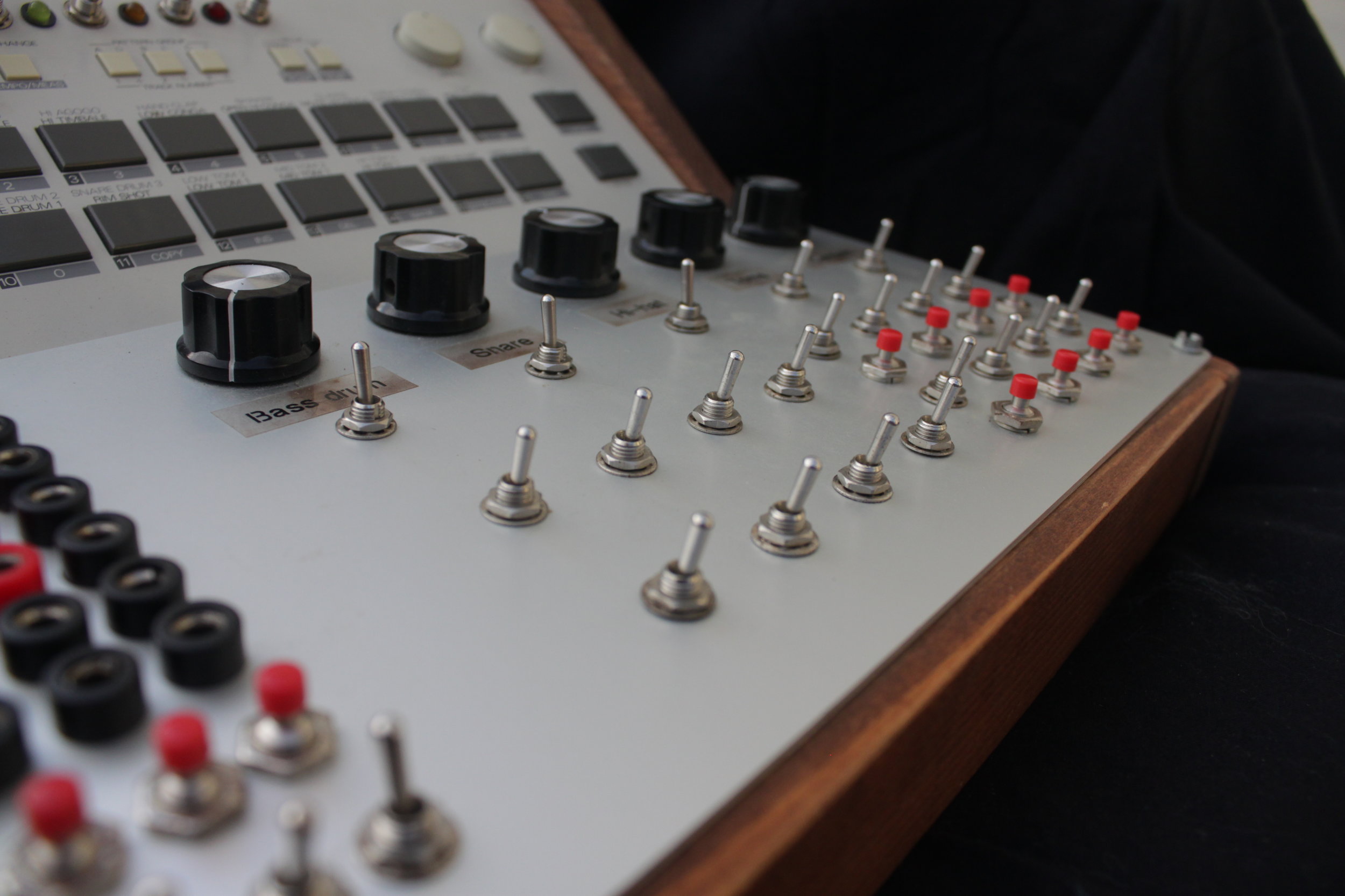
Individual volume control
The only way to directly control the volume of individual drum kit sounds is by programming it in. Very limiting. The TR-626 has individual outputs for each drum kit sound which does help the mixing process out, but when performing it's much easier to have the ability to bring certain sounds in and out directly from the instrument. Using the same resistor bank from above in the patch bay, you can add volume controls for each of the noted kit sounds.

This is how the kick drum volume control is wired. Simply repeat for the other individual kit sounds. The potentiometer will range from muted in the leftmost position and loud and crunchy on the very right, with standard volume falling right around the 12 o'clock position. Shorting R97 and R105 makes a shortcut to the muted position on the potentiometer, so I've also added an on/off switch to act as a hard mute.
Kit Switches
These are taken directly from Burnkit2600's IC15 map. These point-to-point connections simply swap out specific sounds for other sounds. Conga becomes snare drum, hihat becomes cowbell, etc... with varying pitch alterations and a bit of strangeness. Using more than one at a time stacks the weirdness. The eight favorites from IC15 I chose to add to my main panel via toggle switches are:
p28+p2 / p29+p2 / p32+p2 / p29+p16 / p30+p16 / p32+p28 / p32+p29 / p32+p30
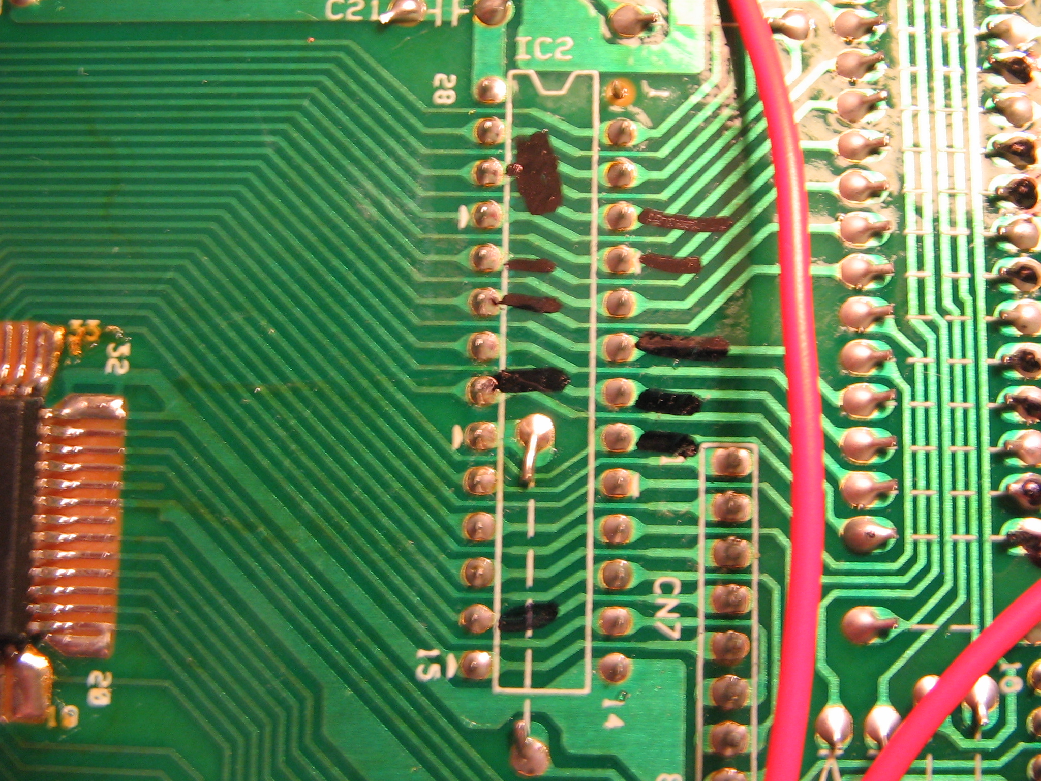
Rhythm Fills
Well, I s'pose some of them work as fills. I added eight switches, as well as momentary push buttons, to engage different "fills." This section is essentially a collection of bends that short out the RAM chip (IC2). This contains the information needed to playback each programmed rhythm, so when these bends are engaged the result are scrambled rhythms, altered kit sounds and pitches, and some other oddities. Throughout most of this excursion the RAM chip was to be avoided due to the instability, but I've found the following combinations to be perfectly stable (though not when combined):
Common point: IC18 pin 8
Pins on IC2: 4, 5, 7, 8, 9, 21, 23, 24
Other pins on IC2 did yield interesting rhythm alterations, but the actual programmed rhythm would also alter and/or corrupt, and often crash the machine.
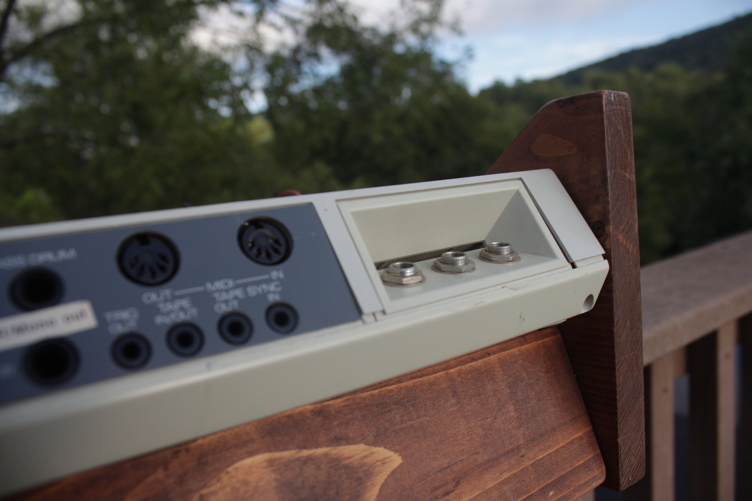
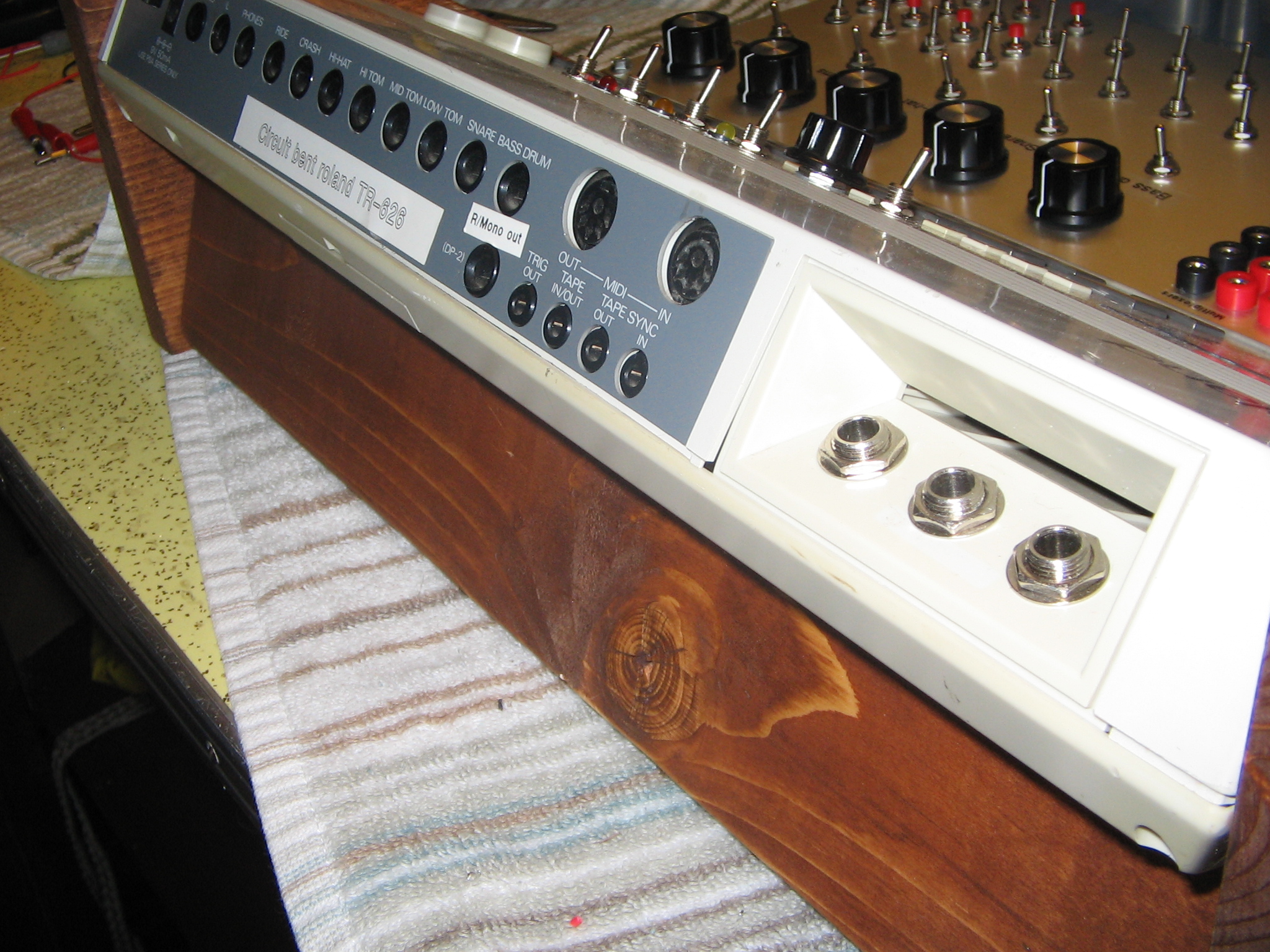
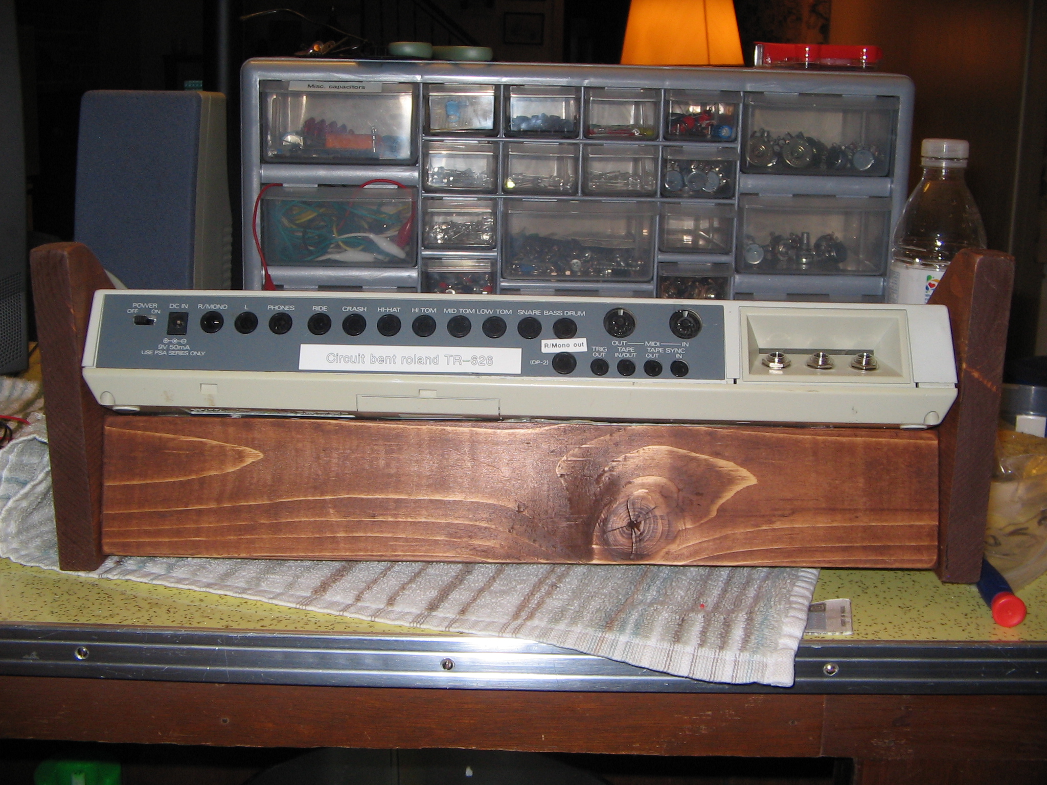
Individual squarewave synthesis outputs
Very simple, very awesome. Individual output jacks for the squarewave synthesis that the 626 is capable of were added (1/4" mono jacks). To add these, wire one pin to ground and the other to IC15 pins 6, 5, 27, 7, 8 and 9. Each pin outputs a different octave, from lowest to highest respectively.
Additional simple point-to-point bends
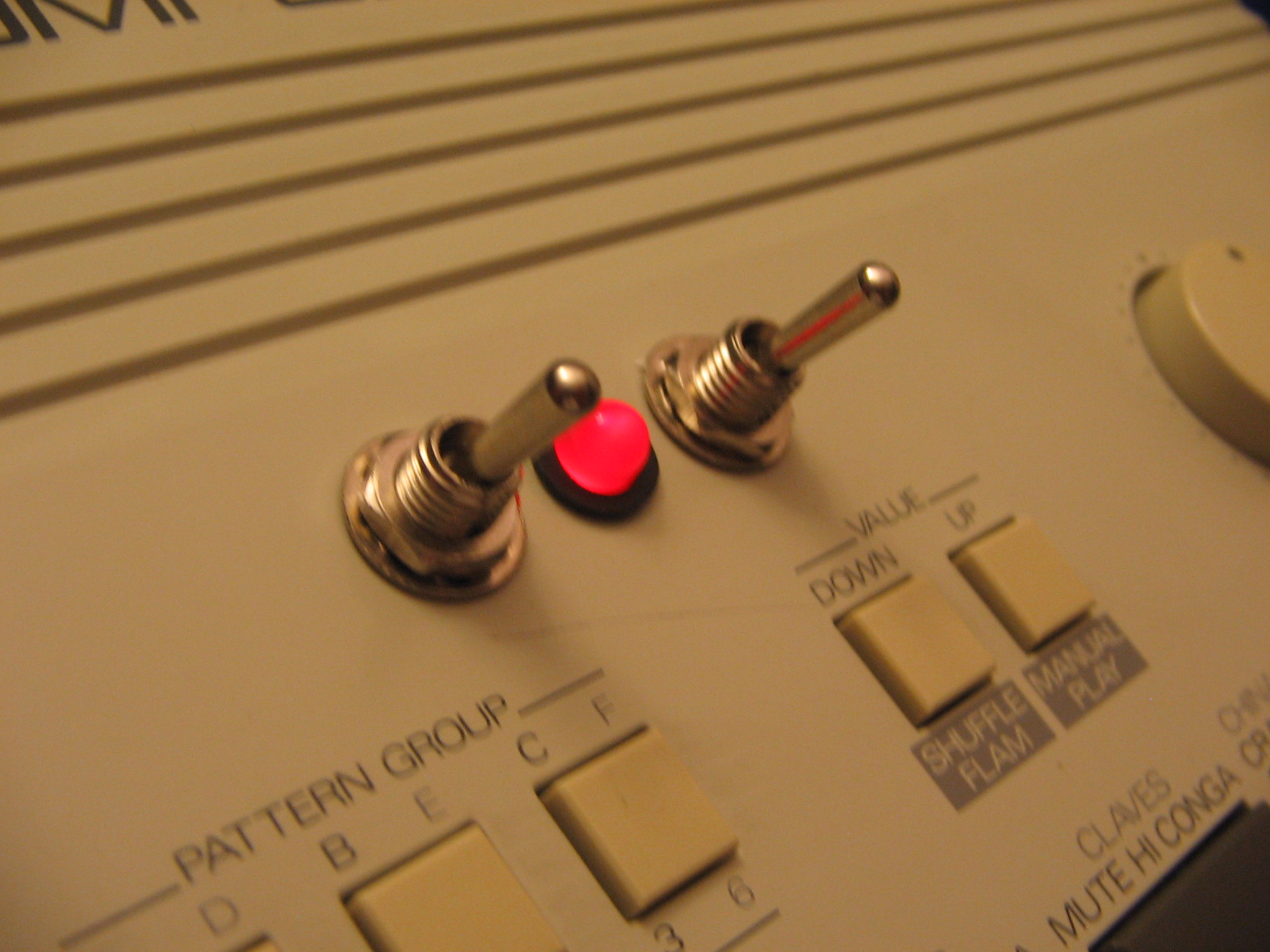
A few additional favorites of mine were added directly to the case of the 626.
IC25 p5 + C71
5k potentiometer and a toggle switch in line for a hard on/off. This is a heavy distortion which also generates some bass tones starting at around 230Hz and going down.
IC5 p24 + IC18 p8
Brings the pitch of all internal sounds way down. I used a toggle switch for this as every potentiometer value I tried showed no potential for variable alteration of pitch, only an on/off area. I was unable to try a potentiometer lower than 1Kohm.
IC15 p20 + IC23 p3 and/or p6
Nice fuzzy, crunchy distortion. Makes the kick drum sounds great. Not 100% sure whether this is pin3 or pin6 due to lack of labeling - the one I used is connected to C43. Both cause a nice distortion, with one being notably heavier.
IC25 p1 + IC16 p6 and/or p3
Gives an odd tremelo/reverse style effect to the toms/timbale's and extends the cutoff time for the ride/crash cymbals, almost indefinitely. Again, not sure whether this is 3 or 6. Counting from the IC16 label it is 6 pins away.
IC15 p5 + C39
I call this the auto-bassline. Generally the squarewave tones that the 626 generates are very sharp and crisp. The tones that this connection produces is seemingly low-pass filtered. It adds a very muddy and deep filtered squarewave under each kit sound. For this a potentiometer would allow for additional control, through I used a simple toggle switch due to space, with a 330ohm resistor in line.
2009.
Note: It can be a lot of work documenting & making guides for builds like this, and credit it is always appreciated. More than anything, however, I’d love to see what you do with my info - if you do use the information on this page, please get in touch with me using the about/contact page; I’d love to see what you create!